
The Engine Shop
Joe Wagner
212 S. Pine Ave., Ozark, AL 36360
Up to now the material in these columns has been mainly aimed at modelers who have had some experience with model engines. But Model Aviation Aeromodeling editor Bob Hunt recently reminded me that many of today’s AMA members start in radio control (RC) without any previous acclimatization period in free flight or control line flying.
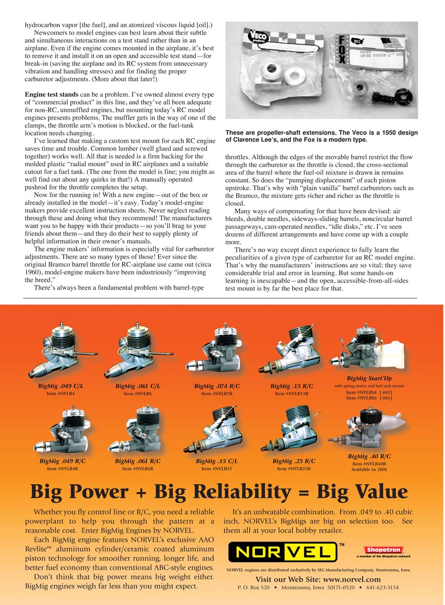
The engines used in those activities provide plenty of scope for modelers to inexpensively accustom themselves to the quirks and sometimes paradoxical behavior of model engines—and even have fun doing so. However, someone who starts in modeling with an almost-ready-to-fly RC trainer can be thoroughly baffled by its engine. I exchanged e-mails with one newcomer who couldn’t keep his RC engine running.
"It starts all right," he wrote. "But as soon as I adjust the needle valve, it slows right down and quits."
In my replies I listed all of the possible problem areas I could think of:
- gasket leakage,
- blown plug seal,
- a cut in the fuel line that allowed air bubbles to enter the fuel stream,
- and more.
I was racking my brain trying to think of other possible causes when a new e-mail arrived from the man. "Sorry I bothered you," he wrote. "I just found out that I'd been adjusting my needle in the wrong direction ..."
Needle valves are apparently so simple! Yet I could write an article twice as long as this column about the various types of needle valves, their advantages and disadvantages, and the maddening problems that result from a bent point or an air leak or a misdirected fuel orifice.
Most sport RC fliers I know don’t care much about the finicky details of what makes their engines run—as long as they do run. And when they don’t run, these fliers want a quick fix much more than they do a lesson in internal-combustion fundamentals.
So many things can go wrong. In two-stroke engines, several interacting processes go on at once while the engine runs. For one, when the piston rises in its cylinder and compresses the fuel-air mixture above it, it’s pulling in a fresh charge below it at the same time. If both processes aren’t close to optimal, the engine won’t run right—at least not for long.
(The term "fuel-air mixture" that is used so readily is an oversimplification. What enters a model engine is akin to what leaves the nozzle of a paint spray gun: a mixture of air, hydrocarbon vapor [the fuel], and an atomized viscous liquid [oil].)
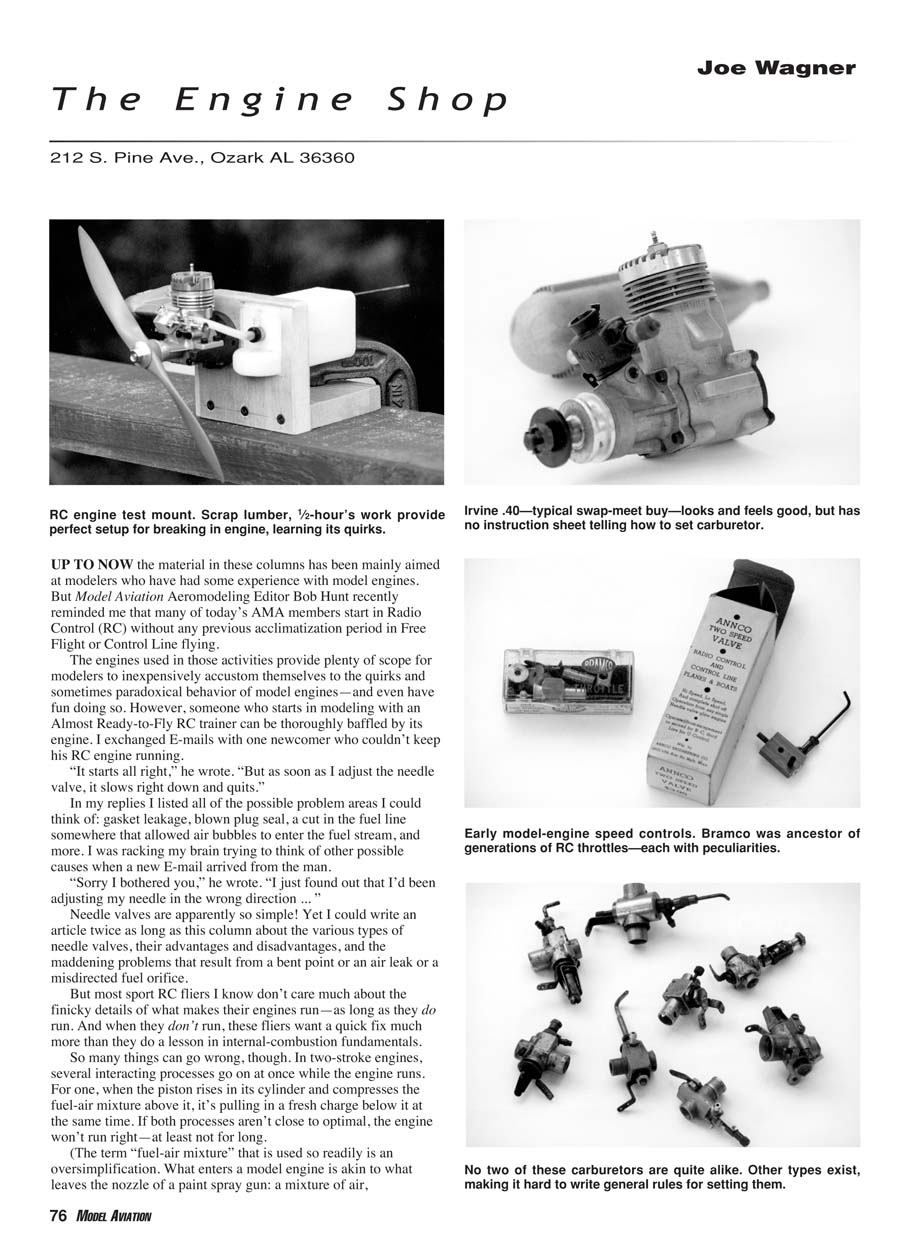
Newcomers to model engines can best learn about their subtle and simultaneous interactions on a test stand rather than in an airplane. Even if the engine comes mounted in the airplane, it's best to remove it and install it on an open and accessible test stand—for break-in (saving the airplane and its RC system from unnecessary vibration and handling stresses) and for finding the proper carburetor adjustments.
Engine test stands can be a problem. I've owned almost every type of commercial product in this line, and they've all been adequate for non-RC, unruffled engines, but mounting today's RC model engines presents problems. The muffler gets in the way of one of the clamps, the throttle arm's motion is blocked, or the fuel-tank location needs changing.
I've learned that making a custom test mount for each RC engine saves time and trouble. Common lumber (well glued and screwed together) works well. All that is needed is a firm backing for the molded plastic "radial mount" used in RC airplanes and a suitable cutout for a fuel tank (the one from the model is fine; you might as well find out about any quirks in that!). A manually operated pushrod for the throttle completes the setup.
Now for the running in! With a new engine—out of the box or already installed in the model—it's easy. Today's model-engine makers provide excellent instruction sheets. Never neglect reading through these and doing what they recommend! The manufacturers want you to be happy with their products—so you'll brag to your friends about them—and they do their best to supply plenty of helpful information in their owner's manuals.
The engine makers' information is especially vital for carburetor adjustments. There are so many types of those! Ever since the original Bramco barrel throttle for RC-airplane use came out (circa 1960), model-engine makers have been industriously "improving the breed."
There's always been a fundamental problem with barrel-type throttles. Although the edges of the movable barrel restrict the flow through the carburetor as the throttle is closed, the cross-sectional area of the barrel where the fuel-oil mixture is drawn in remains essentially constant. So does the "pumping displacement" of each piston upstroke. That's why with "plain vanilla" barrel carburetors such as the Bramco, the mixture gets richer and richer as the throttle is closed.
Many ways of compensating for that have been devised:
- air bleeds,
- double needles,
- sideways-sliding barrels,
- noncircular barrel passageways,
- cam-operated needles,
- "idle disks",
- etc.
I've seen dozens of different arrangements and have come up with a couple more.
There's no way except direct experience to fully learn the peculiarities of a given type of carburetor for an RC model engine. That's why the manufacturers' instructions are so vital; they save considerable trial and error in learning. But some hands-on learning is inescapable—and the open, accessible-from-all-sides test mount is by far the best place for that.
Transcribed from original scans by AI. Minor OCR errors may remain.

