

The Engine Shop
212 S. Pine Ave., Ozark, AL 36360
Reader feedback and the F&G test stand
In recent weeks readers have sent me some extremely cogent and helpful input on topics I mentioned in previous columns, such as the revolutionary new British-made RCV four-stroke engines.
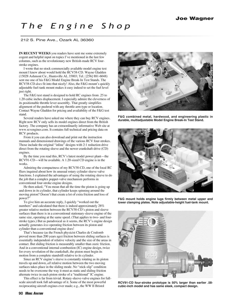
I wrote that no stock commercially available model-engine test mount I knew about would hold the RCV58-CD. Wayne Gladden (15028 Ashmont Cir., Huntsville, AL 35803; Tel.: (256) 881-6048) sent me one of his F&G Model Engine Break-In Test Stands. The RCV58-CD does fit into that nicely! Also, the F&G mount's quickly adjustable fuel-tank mount makes it easy to set the fuel level just right.
The F&G test stand is designed to hold RC engines from .25 to 1.20 cubic inches displacement. I especially admire the cleverness of its positionable throttle-lever assembly. That greatly simplifies alignment of the pushrod with any throttle-arm type or location. Contact Wayne Gladden for pricing and availability of the F&G test stand.
Where to buy RCV engines
Several readers have asked where they can buy RCV engines. Right now RCV only sells its model engines direct from the British factory. The company has an extraordinarily informative website at www.rcvengines.com. It contains full technical and pricing data on RCV products.
From the site you can also download and print the instruction manuals and dimensioned drawings of the various RCV four-strokes. Those include the original "inline" designs with 2:1 reduction drive direct from the rotating sleeve and the newer crankshaft-drive (CD) engines.
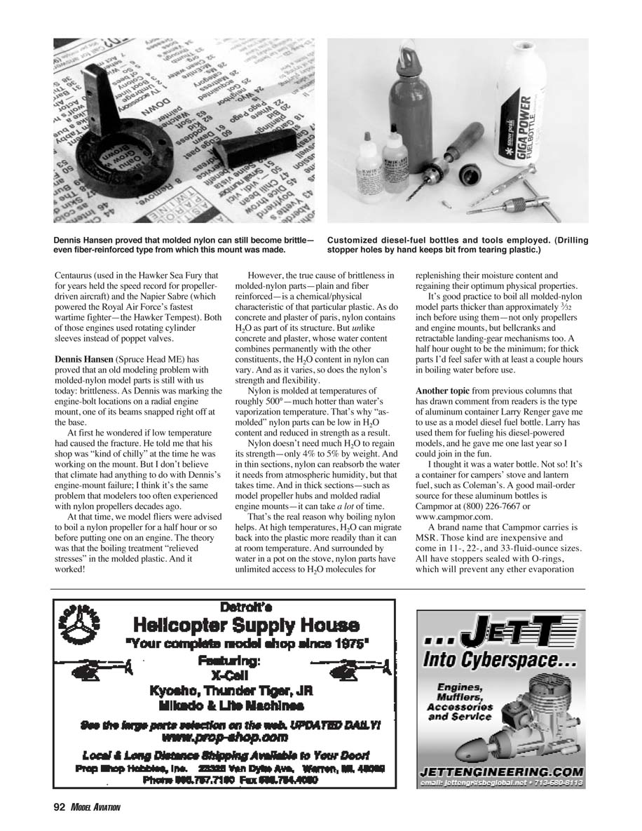
By the time you read this, RCV's latest model power plant—the RCV91-CD—will be available. A 1.20-sized CD engine is in the works.
Rotary sleeve-valve operation and friction
Admiring the compactness of my RCV58-CD, one of the local RC fliers inquired about how its unusual rotary cylinder-sleeve valve functions. I explained the advantages of using the rotating sleeve to do the job that a complex poppet-valve mechanism performs in conventional four-stroke engine designs.
He then asked, "You mean that all the time the piston is going up and down in its cylinder, that cylinder keeps spinning around the moving piston? Doesn't that create a lot of extra friction and loss of power?"
To give him an accurate reply, I quickly worked out the numbers and calculated that there is indeed approximately 28% greater relative motion between the RCV58-CD's piston and sleeve surfaces than there is in a conventional stationary-sleeve engine of the same size, operating at the same speed. (That applies to two- and four-stroke types.) But as paradoxical as it seems, the RCV's engine design actually generates less operating friction between its piston and cylinder than a conventional engine does!
That's because, as the French physicist Charles de Coulomb proved more than 200 years ago, friction between sliding surfaces is essentially independent of relative velocity and the size of the areas in contact. But sliding friction is measurably smaller than static friction. In a conventional internal-combustion (IC) engine design, twice for every revolution of the crankshaft the piston must begin its motion from a complete standstill relative to its cylinder. Since an RCV engine's sleeve is constantly rotating as its piston travels up and down, all relative motion between the two moving surfaces takes place in the sliding mode. No "stick-slip" condition needs to be overcome the way it must as static and sliding friction alternate twice in each piston stroke of a traditional IC engine.
This effect is far from trivial. Rotary-sleeve-valve engines for full-scale aircraft took full advantage of it. Some of the most powerful reciprocating aircraft engines ever made—e.g., the World War II Bristol Centaurus (used in the Hawker Sea Fury, which for years held the speed record for propeller-driven aircraft) and the Napier Sabre (which powered the Royal Air Force's fastest wartime fighter, the Hawker Tempest)—both used rotating cylinder sleeves instead of poppet valves.
Brittleness in molded-nylon parts
Dennis Hansen (Spruce Head, ME) has proved that an old modeling problem with molded-nylon parts is still with us today: brittleness. As Dennis was marking the engine-bolt locations on a radial engine mount, one of its beams snapped right off at the base.
At first he wondered if low temperature had caused the fracture. He told me that his shop was "kind of chilly" at the time he was working on the mount. I don't believe climate had anything to do with Dennis's long-term failure; I think it's the same problem modelers too often experienced with nylon propellers decades ago.
Back then, we were advised to boil a nylon propeller for a half hour or so before putting one on an engine. The theory was that the boiling treatment "relieved stresses" in the molded plastic. And it worked.
However, the true cause of brittleness in molded-nylon parts—plain and fiber-reinforced—is a chemical/physical characteristic of that particular plastic. As do concrete and plaster of Paris, nylon contains H2O as part of its structure. But unlike concrete and plaster, whose water content combines permanently with the other constituents, the H2O content in nylon can vary. As it varies, so does the nylon's strength and flexibility.
Nylon is molded at temperatures of roughly 500°F—much hotter than water's vaporization temperature. That's why "as-molded" nylon parts can be low in H2O content and reduced in strength as a result.
Nylon doesn't need much H2O to regain its strength—only 4% to 5% by weight. In thin sections, nylon can reabsorb the moisture it needs from atmospheric humidity, but that takes time. In thick sections—such as model propeller hubs and molded radial engine mounts—it can take a lot of time.
That's the real reason why boiling nylon helps. At high temperatures, H2O can migrate back into the plastic more readily than it can at room temperature. Surrounded by water in a pot on the stove, nylon parts have unlimited access to H2O molecules for replenishing their moisture content and regaining their optimum physical properties.
It's good practice to boil all molded-nylon model parts thicker than approximately 3/32 inch before using them—not only propellers and engine mounts, but bellcranks and retractable landing-gear mechanisms too. A half hour ought to be the minimum; for thick parts I'd feel safer with at least a couple of hours in boiling water before use.
Aluminum fuel bottles for model diesel fuel
Another topic from previous columns that has drawn comment is the type of aluminum container Larry Renger gave me to use as a model-diesel fuel bottle. Larry has used the item for fueling his diesel-powered models, and he once lent me one last year so I could join in the fun.
I thought it was a water bottle. Not so! It's a container for campers' stove and lantern fuel, such as Coleman's. A good mail-order source for these aluminum bottles is Campmor at (800) 226-7667 or www.campmor.com.
A brand name that Campmor carries is MSR. Those bottles are inexpensive and come in 1-, 2-, and 3-fluid-ounce sizes. All have stoppers sealed with O-rings, which will prevent ether evaporation.
I've modified two of these aluminum fuel bottles for use with my "never-open" diesel filling and fueling technique. My customization method is to hand-drill and tap a pair of #10-32 holes in the stopper. In those I install fueling tubes that I modify from stock 3/4-inch-long brass screws. I epoxy those into place in the stopper to make sure of an evaporation-proof seal.
In use at the field, after filling the bottle I connect the two fueling-tube ends with a length of plastic tubing. Vinyl, Tygon, or neoprene work fine, but neither rubber nor silicone tubing can stand exposure to the kerosene content of model diesel fuel.
To refuel a model, I pull free one end of the plastic tubing on the bottle and attach that to the model's fuel-tank fitting. Then I tilt the bottle and let gravity do the transfer. Air will vent freely into the open tube in the bottle as the fuel passes into the model's tank.
To fill the diesel-fuel bottle itself, I use the same technique. I've modified a one-gallon metal fuel-can cap with two diametrically opposite soldered-in brass tubes, and I gravity-pour fuel from the gallon-size "commercial can" into the smaller fuel bottle the same way I fill a model's tank from the bottle.
Handling model diesel fuel this way stops ether evaporation almost perfectly. It has eliminated the strong aroma in my model shop that used to inform everyone who came into it that I'm a habitual flier of diesel-powered model airplanes.
—MA
Transcribed from original scans by AI. Minor OCR errors may remain.

