
Fuel-line restriction problems
Joe Wagner | [email protected]
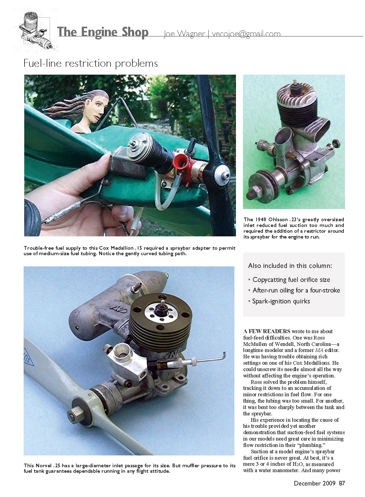
A few readers wrote to me about fuel-feed difficulties. One was Ross McMullen of Wendell, North Carolina—a longtime modeler and a former MA editor. He was having trouble obtaining rich settings on one of his Cox Medallions: he could unscrew its needle almost all the way without affecting the engine’s operation.
Ross solved the problem himself, tracking it down to an accumulation of minor restrictions in fuel flow. For one thing, the tubing was too small. For another, it was bent too sharply between the tank and the spraybar.
His experience in locating the cause provided yet another demonstration that suction-feed fuel systems in our models need great care in minimizing flow restriction in their “plumbing.” Suction at a model engine’s spraybar fuel orifice is never great — at best it’s only 3 or 4 inches of H2O, as measured with a water manometer. Many power plants have oversized intake passageways to maximize power output. An internal-combustion engine’s power depends on how much air it can “inhale.” Oversized inlets tend to minimize suction at the spraybar because they reduce inlet air velocity. That’s why muffler-pressurized setups can be so helpful in achieving reliable fuel delivery into our engines.
Even with muffler pressure, use the largest-size fuel tubing that will fit, make certain there are no kinks in the brass tubing in the tank, and eliminate long, complicated tubing paths between the tank and the engine. When the tubing installation in your airplane is complete, blow through it to make sure the flow is as free as you can manage.
Veco spraybar anecdote
This topic reminds me of something from my Veco days. I was working with Mel Anderson (who designed the Super Cyclone, Anderson Spitfire, Baby Spitfire, etc.) on the Veco .35. While discussing desirable features of the new Veco engine, I mentioned to Mel that every model power-plant spraybar I’d ever checked had the same-size fuel orifice: .040 inch in diameter, for a #60 drill.
Mel told me that while he was working out production design in 1935 for the Baby Cyclone .36 (the first of the West Coast model engines), he decided, for no particular reason, to use the smallest-size drill bit he had for the fuel orifice. Evidently all of the other engine makers either copied the Baby Cyclone’s spraybar setup or chose a #60 drill for the same reason.
He and I experimented and found that a larger fuel orifice worked better in Veco glow engines. No doubt that was because the all-castor-oil-lubed fuel everyone used back then in glow engines was more viscous than the 3:1 white gas to 70-weight oil fuel blend that had long been standard for spark-ignition engines.
Four-stroke lubrication and crankcase breather
I’ve received several inquiries from readers about four-stroke engine lubrication: how oil can get into the crankcase during running, the purpose of the crankcase breather, and how to inject after-run oil into the case to prevent bearing rust.
The main purpose of a four-stroke’s crankcase breather port is to permit lubrication of the shaft, bearings, gears, cam, and pushrods. In a two-stroke, the fuel-oil-air mixture passes through the crankcase before entering the combustion chamber; thus its oil content lubricates all of the lower-end moving parts directly before the fresh mixture flows through the bypass and into the combustion chamber.
A four-stroke doesn’t work that way: the fuel-oil-air mixture goes straight into the head’s combustion chamber. Direct lubrication of the lower end is therefore impossible from the intake mixture. Instead, combustion-chamber pressure during the power stroke forces oil through the tiny clearance space between the piston OD and the cylinder bore into the crankcase interior — provided there is a vent in the case to permit that flow. Without a vent, no throughflow would be possible.
Therefore, although it might be tempting to seal off a four-stroke’s crankcase vent to eliminate messy dripping, don’t do it. Connecting a short length of fuel tubing to the vent nipple and leading that “overboard” is fine, but do not block or obstruct the vent.
A reader suggested connecting a four-stroke’s vent to its intake so the oil emerging from the vent could be burned instead of wasted. That’s a mistaken notion. The oil from the case vent has already done its intended job of lubricating the lower-end parts and needs to exit the case to make room for fresh oil. Also, oil used in model engines should never be burned — it’s there to lubricate, not to provide extra fuel.
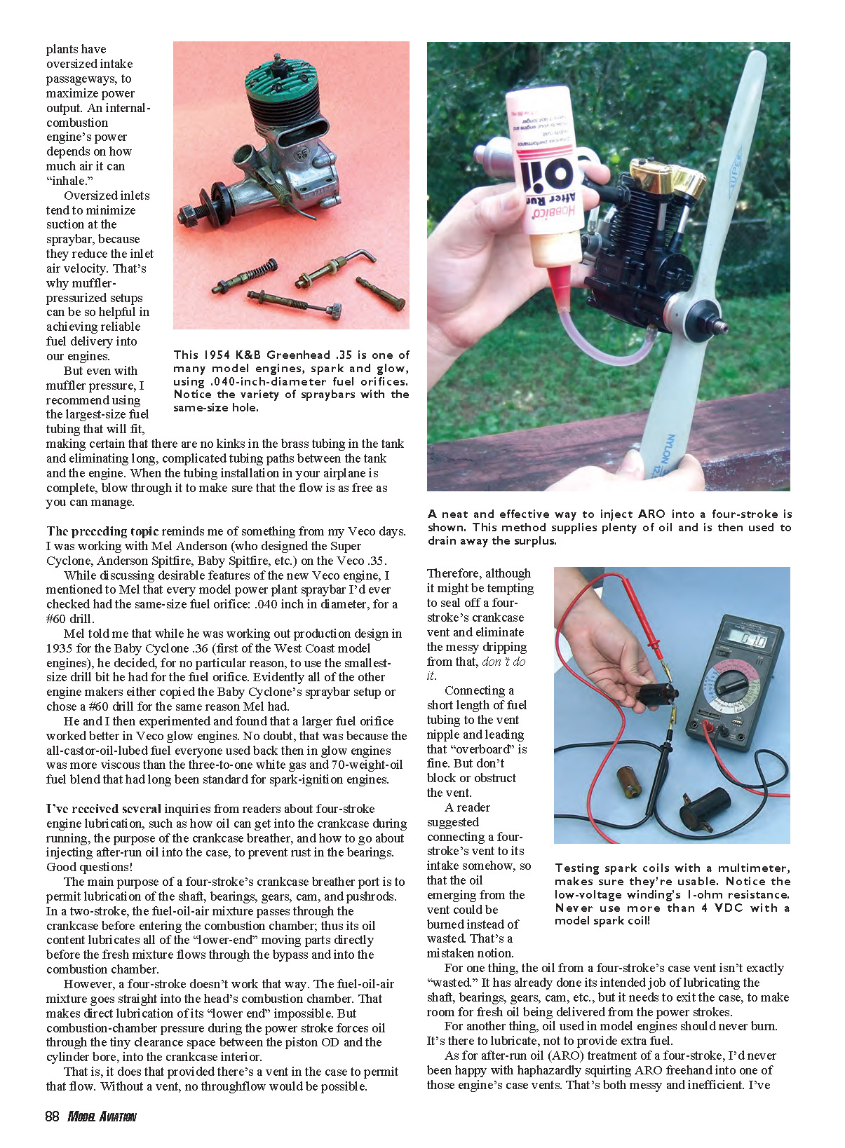
After-run oil (ARO) technique
I wasn’t happy with haphazardly squirting ARO freehand into a four-stroke’s case vent — it’s messy and inefficient. Here’s a neater procedure that works well:
- Slice off the plastic-bottle nozzle of a Tower Hobbies ARO a bit at a time until the hole in its end fits firmly over a 4-inch length of medium-size silicone fuel tubing.
- With the engine upright, push the end of the ARO tubing onto the vent nipple.
- With the ARO bottle upside down, gently rotating the engine’s propeller draws in quite a lot of ARO on the piston’s upstroke, even without squeezing the bottle.
- Shake and twist the engine to distribute the ARO throughout the case interior so the oil reaches all moving parts.
- Turn the engine and the ARO bottle back to an upright position and briskly flip the propeller to force the surplus ARO back into its bottle. Loosen the bottle’s top slightly to avoid “inflation.”
Spark coils — old vs. new, failures, and testing
Some readers have asked about old-time spark-ignition components: how to tell whether old coils are still good and how today's coils compare to Smith, AeroSpark, and OK coils from the past.
Modern coils — such as those available from Larry Davidson — work as well as the larger, heavier coils of the past, although their winding ratios are far different. Today's transistorized spark-ignition modules plus Ni-Cd batteries eliminate most of the problems we had with the original Kettering spark circuitry and its unreliable condensers and pencell batteries.
However, coils — old or new — do fail, and the main reason is overheating. A typical model spark coil’s primary windings have a resistance of only about 1 ohm. That means with a 3-volt input, about 3 amperes pass through the coil, and the coil must dissipate roughly 9 watts of heat energy whenever the engine’s points are closed. Excessive input voltage or too many battery cells can melt impregnation wax, burn insulation, or even burn the windings themselves.
Larry’s newer coils are designed to use three Ni-Cd cells in series; even when fully charged that battery pack won't harm one of his coils.
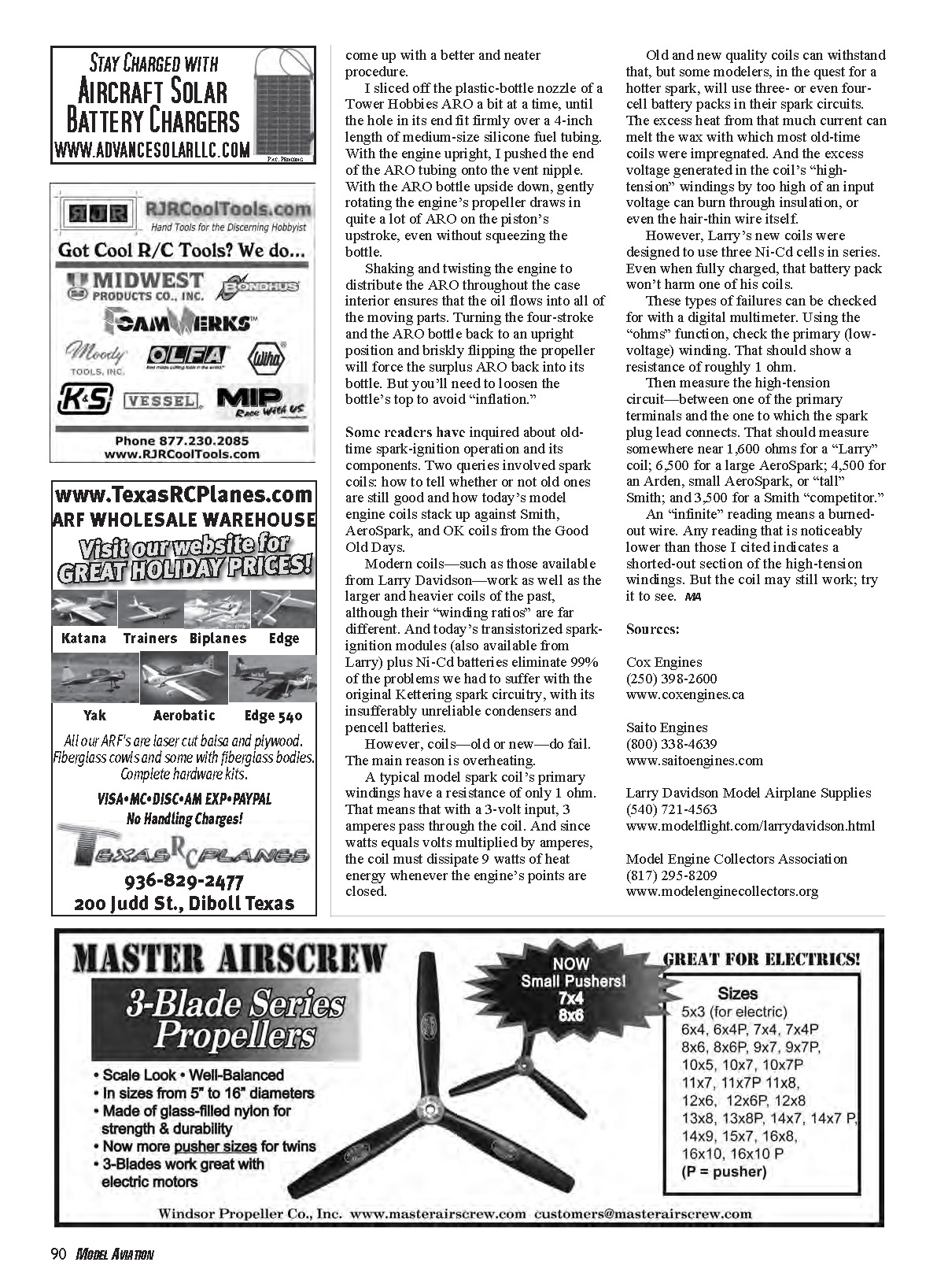
Checking coils with a digital multimeter
Use the ohms function on a DMM to check coils:
- Primary (low-voltage) winding: roughly 1 ohm.
- High-tension circuit (between one primary terminal and the terminal to which the spark plug lead connects):
- ~1,600 ohms for a "Larry" coil
- ~6,500 ohms for a large AeroSpark
- ~4,500 ohms for an Arden, small AeroSpark, or "tall" Smith
- ~3,500 ohms for a Smith "competitor"
An "infinite" reading means a burned-out wire. Any reading that is noticeably lower than those cited indicates a shorted section of the high-tension windings. That said, a coil with an abnormal reading may still work — try it to confirm.
Sources:
- Cox Engines — (250) 398-2600 — www.coxengines.ca
- Saito Engines — (800) 338-4639 — www.saitoengines.com
- Larry Davidson Model Airplane Supplies — (540) 721-4563 — www.modelflight.com/larrydavidson.html
- Model Engine Collectors Association — (817) 295-8209 — www.modelenginecollectors.org
Transcribed from original scans by AI. Minor OCR errors may remain.

