
The engineering behind MULTICOPTERS
A mechanical engineering student shares his data on multicopter design
by Paul Coco
Since the explosion of multicopters, there has been little mention of how to properly design the frame or account for the aerodynamics. There have been multiple blogs and articles, which rely on rules of thumb and experience to determine the proper materials needed to construct the frame or the length of your rotor arms.
Even when accounting for aerodynamics, most people only take into perceptive the lift and power of a multicopter. Optimizing your flight envelope can maximize your lift, flight duration, and forward speed.
A well-engineered frame can increase the efficiency of any multicopter and reduce the level of noise or excess signals to gyros and accelerators, compensating for vibrations. The main source of vibrations on a multicopter comes from the motors and the propellers. Based on the material selected for your frame and rotor arm length, these vibrations could be absorbed or amplified.
Within the course of graduate study for mechanical engineering, I related principles of vibrational analysis, aerodynamics, and fracture mechanics to design the best frame for a tricopter. Most people can overcome the design of the frame by adjusting the proportional, integrated, and derivative controls (PIDs), or by placing an anti-vibration pad under their flight controls, but this may not always give you the proper feel to fully enjoy your flying experience.
The tricopter's frame was composed of materials chosen for strength, weight, and flexibility. In any design of a machine capable of flight, weight must be strongly considered. The three materials that I evaluated for the tricopter's frame were wood, aluminum, and carbon fiber (Graph A). G-10 plastic is another popular choice, but it was not commercially available in the same dimensions as the other material.
The first aircraft were constructed from wood, which then evolved to aluminum and aluminum alloys. In today's aircraft, aluminum components are being replaced with carbon fiber. Because tricopters are exposed to cyclic stresses and vibrations, a cyclic-fatigue analysis and a vibration-test analysis were completed on the candidate material to determine which would perform the best (Graph B).
Fatigue occurs when a material is subjected to repeat loading and unloading. If loads are above a certain threshold, microscopic cracks begin to form at the surface. A crack will eventually reach a critical size, and the structure will suddenly fracture.
The cyclic fatigue can be analyzed from material properties and a given flaw size in the structure. The cyclic loads that would be experienced on the tricopter are the vibrations from the motor and the loads that occur in flight from the force and torque generated by the propellers. Because of the magnitude of each cyclic stress, failure from fracture would most likely occur from flight loads on the frame.
While the frame undergoes this process, failure can be accelerated by hard landings and crashes. To attach the rotor arms to the center plate and to the motors, small, round holes were drilled to bolt the components in place. The anchor holes drilled into the material constituted the given flaw size for the fatigue calculations.
An adhesive would have been a better option to eliminate the flaw size, but if a rotor arm was replaced because of damage from a test flight, then completing the repair could cause further damage.
The fatigue analysis was completed based on the ultimate tensile strength of each material. This corresponds with the maximum load placed on the material to cause failure before any cyclic loading. The analysis is based on a crack growth or damage tolerance analysis, which is concerned with the number of cycles until fracture. This analysis creates a plot that shows a decrease in the ultimate tensile strength of the materials.
Carbon fiber had the greatest ultimate tensile strength of the candidate materials, and wood the least. Based on the analysis plotted, carbon fiber also had the best fatigue life, but it also had the greatest initial crack growth propagation.
It was also observed from the plots, and is a known material advantage, that wood initially had the most resistant crack growth, but was surpassed by carbon fiber in later cycles. To achieve the best attributes of the strongest material and the smallest crack growth propagation, a composite of wood and carbon would be ideal for any applications that require anchor holes to be drilled into the material for mounting.
The carbon-fiber beams used were 10.5mm square with an 8mm circular, hollowed-out cross section. An 8 mm wooden dowel was glued inside the carbon-fiber beam. This was done with the intent of the wood reinforcing the crack growth of the carbon fiber from the anchor points. A cross section of this composite is illustrated and was used as the rotor arm of the tricopter.
The entire tricopter can be modeled as a spring-mass dampener system, in which a single rotor arm can be analyzed to determine the appropriate candidate material for construction of the frame, based on material vibration characteristics. The main source of all vibrations is assumed to come from the motors operating at various throttle ranges. If the propellers are dynamically balanced, they will amplify the forces because of vibrational accelerations created by the motors.
A test frame was constructed to dynamically isolate a motor. A vibration-measuring device installed at the base of the motor measured vibrations throughout the entire throttle range. The vibration-measuring device was made for an analog three-channel data logger and a three-axis accelerometer, both powered by a small LiPo. Information was uploaded from the data logger to a computer for data analysis. The data provided was in G-forces, which corresponds to one acceleration of gravity or 32.2 ft./s2. By multiplying the mass of the motor by the accelerations, force is obtained. Because the mass of the logger was equal to the mass of the motor’s propeller adapter, the test was conducted without the propeller adapter without the need for correction of the mass of the measuring device in the analysis.
To ensure that the motor was properly and dynamically isolated in the test frame, a second vibration-measuring device was used to observe that no motor vibrations were dissipated through the frame. The second vibration measuring device was an iPhone 4, which contains a three-axis gyro and a three-axis accelerometer, and an app was used to measure the vibrations. The iPhone was placed on the inner part of the test frame and indicated that the frame was dynamically isolating the motor during testing.
The motor used for the vibration test was a Scorpion SII-3026-08 (950KV) with an APC 11x4.7 propeller. The motor was mounted to the adapter and balanced with a propeller on the motor. The motor was run at various throttle settings while the data logger recorded the accelerations. Frequency analysis was performed on the logged data to determine the dominant frequencies generated by the motor and propeller combination.
The data showed that the dominant frequencies were harmonically related to the motor RPM and the number of blades on the propeller. The amplitudes of the vibrations varied with throttle setting, and resonance peaks were observed at certain RPM ranges. These resonance peaks correspond to critical speeds where the structural response of the rotor arm would be amplified, potentially leading to fatigue failures if the natural frequencies of the arm matched the excitation frequencies.
Finite element analysis (FEA) was also performed on the rotor arm designs to determine the natural frequencies and mode shapes. The FEA results were compared with the experimental vibration data to validate the models. Using the validated models, design modifications were made to shift the natural frequencies away from the excitation frequencies and to reduce stress concentrations at the anchor holes.
Field testing of the tricopter with the carbon-wood composite rotor arms showed improved durability and resistance to crack propagation compared with pure carbon-fiber arms that contained drilled anchor holes. The composite arms also provided sufficient stiffness and reduced weight, contributing to overall vehicle performance.
Photos and schematics of the test setups, composite cross sections, and FEA mode shapes are included to illustrate the findings and to guide practitioners in selecting materials and designing rotor arms to minimize fatigue-related failures in multicopters.
A second data logger was used in the smart-brain ESC to record voltage, rpms, and throttle as the motor was run without a propeller through a range of throttle positions.
Four motors were tested using this method. The resultant accelerations from the X, Y, and Z axes were combined and plotted against the percentage of throttle (Graph C), which produced a graph that plotted vibrations at various throttle ranges, developing a motor profile. The results were plotted with a moving average trend line. The highest vibration spikes occurred at the 57% and 80–100% throttle positions.
This information was useful to determine the proper throttle ranges to operate in a hover condition, which may require minimized vibrations, and to ensure that the rpms related to the throttle position do not coincide with the natural frequency of the candidate materials to be used for the rotor arms.
Because the test was conducted without propellers or essentially in no-load conditions, the rpms were used to correctly identify the occurrence of the vibration spikes. Different propellers on the motor will increase the loading while decreasing the rpms. For example, the no-load maximum was approximately 12,000 rpms. While loaded, the maximum was 8,350 rpms. Both corresponded to 100% throttle (Graphs D and E).
Because the propellers are dynamically balanced, it is assumed little to no vibrations were caused by the propellers. Vibration spikes observed in the no-load condition would occur at the same rpms when loaded.
The relationship between motor voltage and rpms is linear. The operator transmitter has the ability to use programmable curves, and the throttle programming normally used in RC helicopter applications was implemented.
Because the motor vibration spikes occurred at 11,200 rpms, 12,000 rpms, and above, these values of rpms were outside the operating range or flight envelope of the loaded motor profile. Any vibration spikes observed on the frame would be a factor of the natural frequency and the length of the rotor arms for each of the candidate materials.
Natural frequency is a function of the rotor-arm length and material properties of each of the candidate materials. To analytically model the rotor arm, a vibration-beam analysis was completed. The dimensions of the rotor arm were best modeled as a cantilever beam fixed on one end and the other free. The mass of the motor was neglected because it provides an upward force from the propellers.
Torque was also neglected because it is small when compared with the thrust. The analysis of a cantilever beam was subjected to free vibration, and considered a continuous system in which the beam mass as distributed along with the stiffness of the shaft.
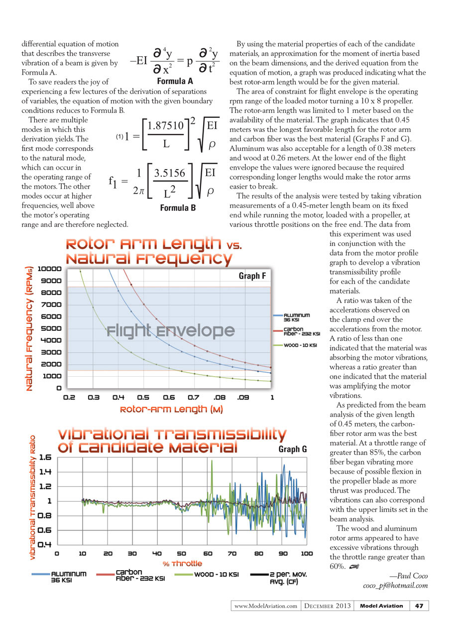
By using the material properties of each of the candidate materials, an approximation for the moment of inertia based on the beam dimensions, and the derived equation from the equation of motion, a graph was produced indicating what the best rotor-arm length would be for the given material.
The area of constraint for flight envelope is the operating rpm range of the loaded motor turning a 10 x 8 propeller. The rotor-arm length was limited to 1 meter based on the availability of the material. The graph indicates that 0.45 meters was the longest favorable length for the rotor arm and carbon fiber was the best material (Graphs F and G). Aluminum was also acceptable for a length of 0.38 meters and wood at 0.26 meters. At the lower end of the flight envelope the values were ignored because the required corresponding longer lengths would make the rotor arms easier to break.
The results of the analysis were tested by taking vibration measurements of a 0.45-meter length beam on its fixed end while running the motor, loaded with a propeller, at various throttle positions on the free end. The data from this experiment was used in conjunction with the data from the motor profile graph to develop a vibration transmissibility profile for each of the candidate materials.
A ratio was taken of the accelerations observed on the clamp end over the accelerations from the motor. A ratio of less than one indicated that the material was absorbing the motor vibrations, whereas a ratio greater than one indicated that the material was amplifying the motor vibrations.
As predicted from the beam analysis of the given length of 0.45 meters, the carbon-fiber rotor arm was the best material. At a throttle range of greater than 85%, the carbon fiber began vibrating more because of possible flexion in the propeller blade as more thrust was produced. The vibrations can also correspond with the upper limits set in the beam analysis.
The wood and aluminum rotor arms appeared to have excessive vibrations through the throttle range greater than 60%.
—Paul Coco coco_pj@<REDACTED>
Transcribed from original scans by AI. Minor OCR errors may remain.

