
Engines 101 Revisited - 2004/08
by Frank Granelli
Introduction and Purpose
Before proceeding to the third article in the "From the Ground Up" engine series, I am going to review the first installment, published in the April issue. MA has received numerous comments on the information presented in that article. Many were favorable, but several pointed out that the theoretical information was incomplete, poorly explained, or just plain wrong. In some instances they had valid points.
The engine theory I present is intended solely to provide beginning RC pilots with enough knowledge of a model engine's workings to understand why choices about proper mixture settings, fuel, propellers, and other items will be made. There is no intent to fully detail an engine's intricate machinery. The new RC pilot is not going to be designing or disassembling (I hope) his or her first few engines, but this person will be setting high- and low-speed mixture settings.
All the theory here is from a strictly operational viewpoint. Proper engine operation is the only goal in this discussion. Where true technical names for parts may be confusing, I use descriptive terms instead. Since most new modelers have no knowledge of two-stroke engines, but do have at least a passing familiarity with their cars' engines, I'll reference parts with more recognizable terms when appropriate.
To simplify the theoretical presentation, I explain each action as if it were the only one happening at that time. Operations that are explained separately and appear independent actually overlap and sometimes interfere with one another. The simplification is intended to help comprehension for beginners.
Terminology and Simplifications
A great deal of confusion would have been avoided if I had started "Engines 101" with the preceding material. Because of the decision to simplify and avoid confusion, the rotary disk induction valve became the crankshaft intake slot. The true engineer's name is correct but leads one to look for a moving valve such as those found in a car or a rotating valve. There isn't one—the "valve" is a slot. The name also sounds as if some sort of "pumping" action is happening when it is not.
Similarly, I discussed "intake" and "boost intake" ports, actually known as transfer (also called bypass) and boost transfer (bypass) ports. Why "transfer"? Because these ports allow the fuel/air mix in the crankcase to transfer from the crankcase to the combustion chamber, but their function is that of fuel/air intake ports.
I also simplified the phrase "partial vacuums" as just "vacuums." Technically these are low-pressure areas since there is nothing approaching a physicist's definition of a partial hard vacuum in our engines—there is just too much gas density everywhere inside.
I omitted detailed discussion of timing advance, all references to Top Dead Center (TDC) operations, and especially references to interference and benefits one operation may have compared with another. None of this theory would help newer RC pilots operate their engines better, and explaining these operationally irrelevant but theoretically important functions would have taken almost a full article themselves.
Fuel Cooling and Refrigeration
In the original article I called methanol in our fuel a "heat exchanger" and pointed out that methanol helps cool the engine; that is why a richer mixture is important. Technically, methanol cools our engines because it has a high heat of evaporation. During carburetor air intake, methanol in the fuel is transformed into a gas requiring a great deal of heat. The process—called evaporation—therefore removes heat from the surrounding lower engine sections to have the energy to transform the methanol.
The same process cools the food in your household refrigerator, but without the combustion part. Your refrigerator substitutes an electrically driven pump and evaporator for crankcase pumping and venturi action at the carburetor. The process is not strictly a heat exchanger action, because a heat exchanger does not transform a substance into another state of matter, it simply transfers heat from one medium to another.
There is, however, a true heat-transfer effect in our engines: oil in the fuel removes heat from the engine and transfers it to the atmosphere via the exhaust. Some oil is not burned during combustion and escapes through the exhaust; while escaping it transfers some of the engine's heat.
The main point remains: whether through evaporation or oil heat transfer, the fuel lubricates and cools our engines. RC engines are not cooled solely through contact with the air; therefore, proper high-speed fuel mixture settings are critical and must not be ignored.
Starting Position and Basic Cycle Overview
I'll start with the piston at Bottom Dead Center (BDC), meaning it is as far down in its movement (stroke) as it can get. The engine has not started and there is no fuel anywhere inside the engine—only in the fuel tank. Operationally, it is important to have fuel in the tank before trying to run the engine.
Starting an engine from BDC is difficult until fuel flows from the tank through the fuel lines and into the carburetor. To draw fuel from the tank into the carburetor we use the "suction" effect generated by the engine during hand-rotation.
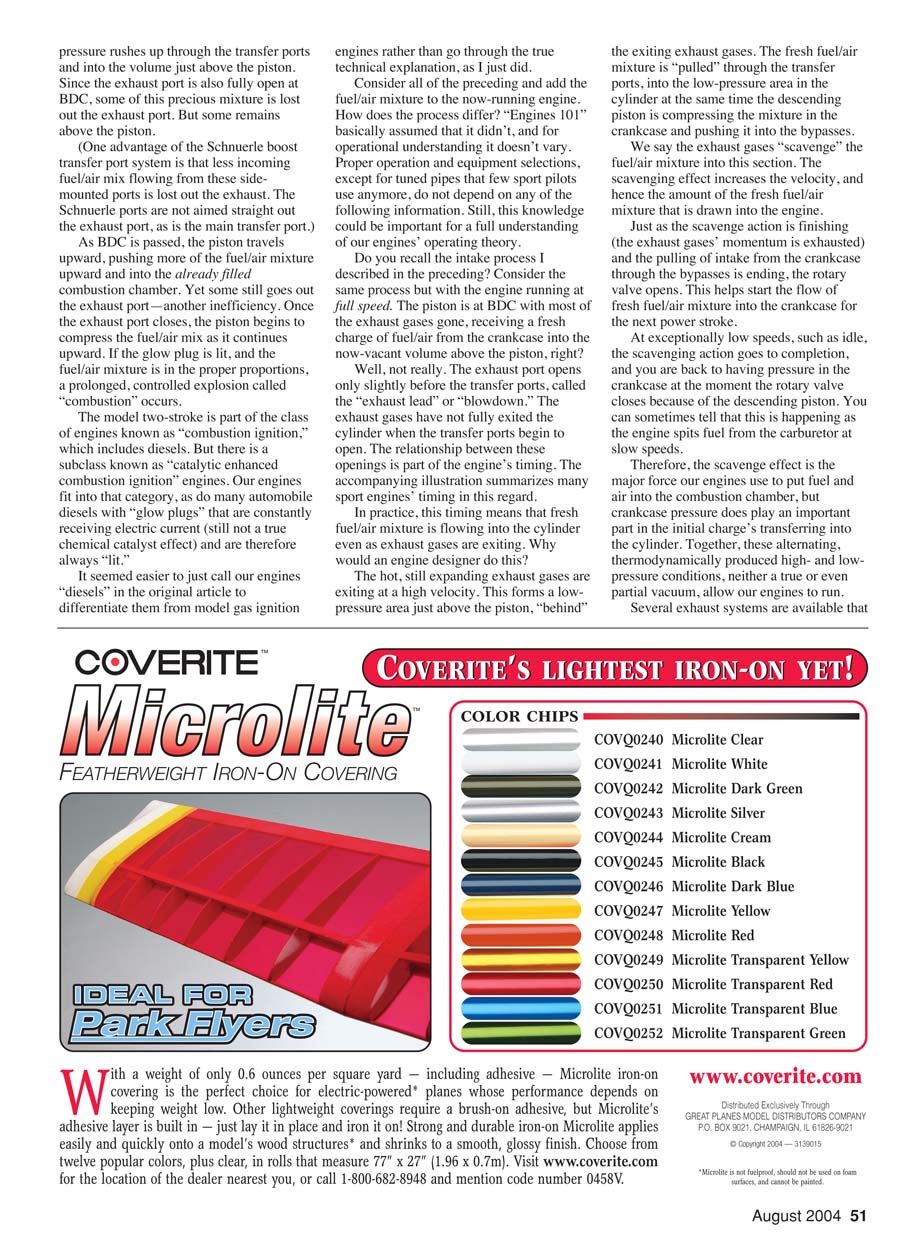
While at BDC the rotary disk induction valve—the intake slot in the crankshaft—is fully closed. As the engine is hand-rotated counterclockwise, the piston begins to move upward. It first closes all the transfer (intake) ports. At this point the rotary valve begins to open, but the exhaust may still be slightly open. However, there is no connection between the exhaust port and the engine's lower crankcase at this point, so that is irrelevant now.
As the piston continues upward, the crankcase volume increases (volume, not area). Because the now-sealed crankcase volume is larger but still contains the same amount of air, the air expands to fill the increased volume and therefore its pressure drops. The rotary valve opens more as the piston travels upward and, if the carburetor throttle is open, air rushes through the carburetor, through the rotary valve, and into the crankcase. When fuel is present this process repeats with a fuel/air mixture.
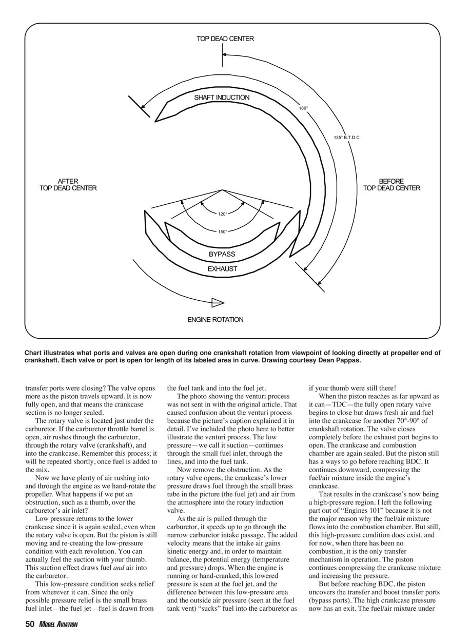
If you obstruct the carburetor air inlet (for example, with your thumb), low pressure returns to the lower crankcase since it is again sealed even when the rotary valve is open. The piston is still moving and re-creating the low-pressure condition with each revolution, and you can feel the suction with your thumb. This suction draws fuel and air into the carburetor. Since the only possible pressure relief is the small brass fuel inlet—the fuel jet—fuel is drawn from the fuel tank through the jet into the carburetor.
As air is pulled through the carburetor, it speeds up through the narrow carburetor intake passage. The added velocity means the intake air gains kinetic energy and, in order to maintain energy balance, the potential energy (pressure and temperature) drops locally. This lower pressure at the fuel jet, compared with the outside air pressure at the fuel tank vent, "sucks" fuel into the carburetor.
When the piston reaches Top Dead Center (TDC), the fully open rotary valve begins to close but draws fresh air and fuel into the crankcase for another 70°–90° of crankshaft rotation. The valve closes completely before the exhaust port begins to open. The crankcase and combustion chamber are again sealed. The piston then travels downward, compressing the fuel/air mixture inside the crankcase, creating a high-pressure region.
Transfer Ports, Boost Ports, and Scavenging
Before reaching BDC on the compression-to-intake movement, the piston uncovers the transfer and boost transfer ports (bypass ports). The high crankcase pressure now has an exit. The fuel/air mixture under pressure flows through the boost port and across the top of the piston into the combustion chamber. This "boost" effect helps scavenge spent exhaust gases and fill the combustion chamber.
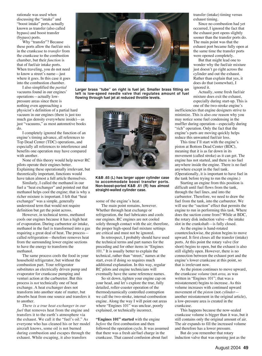
At BDC the exhaust port is generally fully open; therefore, some of the fresh mixture is lost out the exhaust. This is one of the two-stroke engine's inherent inefficiencies. The shape and timing of the ports determine how much mixture is transferred and how well the engine scavenges. Different engines use different arrangements: some have wide boost ports, others narrow ones or none at all; some have multiple transfer ports to provide broader distribution of flow and improve scavenging. One advantage of Schnuerle boost transfer port systems is that less incoming mixture flows straight out of the exhaust because the ports are angled to direct flow across the cylinder rather than directly toward the exhaust.
As the piston passes BDC and travels upward, it pushes more of the fuel/air mixture upward into the combustion chamber. Some still goes out the exhaust port—another inefficiency. Once the exhaust port closes, the piston begins to compress the fuel/air mix as it travels upward. If the glow plug is hot and the mixture proportions are correct, combustion will occur shortly after the piston reaches TDC on the compression stroke.
Scavenging During Running and the Role of Exhaust Momentum
When the engine is running at speed, the exhaust port opens slightly before the transfer ports—this is called "exhaust lead" or "blowdown." Usually the exhaust gases have not fully exited the cylinder when the transfer ports begin to open. The hot, still-expanding exhaust gases exit at high velocity and form a low-pressure area just above the piston behind the exiting gases. The fresh fuel/air mixture is pulled through the transfer ports into that low-pressure area even as the crankcase compresses and pushes fresh mixture into the bypasses.
This scavenging effect—the momentum of the exiting exhaust gases pulling fresh charge in—is the major force used to fill the combustion chamber, though crankcase pressure contributes to the transfer as well. At very low speeds (idle) the scavenging can go to completion and crankcase pressure may be present at the moment the rotary valve closes; you can sometimes tell because the engine spits fuel at slow speeds.
Several exhaust systems aim to separate exhaust gases from the incoming fresh charge by using transfer-port timing and piping to take advantage of pressure waves in the exhaust. Tuned pipes, for example, form a pressure wave that can return partially burned gases toward the cylinder just after the exhaust port closes and before the transfer ports have fully closed. When properly tuned for a given rpm range, the returning wave timing helps keep exhaust products out of the cylinder and push more fresh mixture in, improving cylinder filling and power. Tuned pipes require precise timing and are most beneficial at higher rpm ranges; at lower rpm the pipe may return exhaust at the wrong time and hurt performance. For general sport flying, simple mufflers or tuned pipes designed for broad ranges are preferred.
Combustion Timing and Advance
Combustion occurs before the piston reaches TDC and continues through TDC and somewhat after. The amount of advance—the degree to which ignition starts before TDC—is a deliberate design choice because combustion takes time; the fuel does not explode instantaneously. The prolonged pressure rise from advanced timing helps extract work from combustion as the piston begins its downward stroke.
Too much advance can damage the piston or cause detonation; too little advance reduces power. Running an engine too lean produces extra heat that can upset this balance. Hot engines can experience effectively advanced timing that leads to detonation—this may be identified by a loud "frying egg" sound (crackling) at full speed. If you hear that, land and readjust the high-speed mixture to richer.
Carburetor Needles and Mixture Adjustment
The low-speed needle, usually on the side of the carburetor, affects the mixture at low throttle settings and during idle. It controls fuel flow into the venturi at small throttle openings. The high-speed needle (main needle) controls the mixture at higher throttle settings and maximum power. Changing these needles changes not only the fuel flow but also the airflow characteristics and therefore the effective venturi action.
When adjusting:
- Set the low-speed needle first to get a smooth idle and good throttle response.
- Then adjust the high-speed needle for full-power richness.
If the high-speed needle is too lean, the engine may overheat or lose power; if too rich, performance will be dull and the glow plug may foul.
Fuel selection and propeller choice are the next topics to be covered in the series.
Additional Clarifications and Technical Notes
- Scavenging losses: During the charge cycle, some fresh fuel/air mixture is drawn out the exhaust along with the escaping gases. This is lost power and poor fuel economy that designers strive to minimize.
- Engine class: Model two-stroke glow engines fall into "combustion ignition" engines. There is a subclass called "catalytic enhanced combustion ignition" engines; our engines fit into that category. Some automobile diesels with glow plugs that are constantly heated resemble this behavior.
- Advance and detonation: Combustion occurring before TDC necessarily pushes against the piston's upward motion for a short time; designers advance ignition to balance the time-required combustion with crankshaft position. Hot or overly lean operation can make detonation more likely.
Corrections to "Engines 101" and Other Errors
Revisiting the original article, I found several errors and oversimplifications. The important operational steps I presented in "Engines 101" were valid, but these comments helped identify areas needing more explanation.
Notable corrections and clarifications:
- Crankcase volume vs. area: I misstated "area" in the original; the correct term is crankcase volume.
- Piston vs. cylinder movement: I incorrectly wrote "cylinder" in one place; I meant piston movement.
- Methanol cooling: I oversimplified by calling methanol a "heat exchanger"; it cools mainly by evaporation (high heat of vaporization).
- Piston/cylinder dimensions (ABC engines): I erred by saying the piston is larger in diameter than its cylinder. In fact, the piston is the same diameter as the cylinder; new engines may have a slightly larger piston by no more than one to two ten-thousandths of an inch, which wears in quickly. The operational point remains that aluminum-brass-chrome (ABC) engines are more tolerant of lean mixtures than ringed engines due to thermal expansion differences.
- Torque comparison: I said four-stroke engines have more torque than equivalent two-strokes. I should have clarified that four-strokes often produce more usable torque at lower rpm for sport fliers; two- and four-strokes have roughly similar maximum torque, but the rpm band where it occurs differs.
- Power comparison: I wrote that, in theory, a two-stroke should have twice the power of an equivalent four-stroke, assuming 100% efficiency. Real engines are far from that efficiency. I also said modern four-strokes have roughly 70%–80% of equivalent two-stroke power; I was considering sport 40–60 engines only. Competition supercharged or fuel-injected four-strokes can approach parity at higher cost.
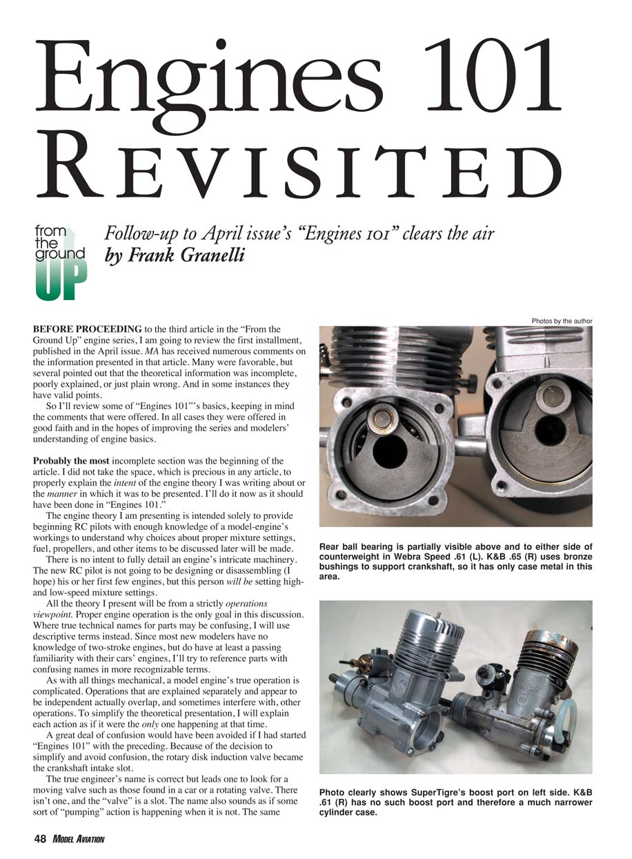
- Bearings vs. bushings: I incorrectly implied ball bearings provide "more" crankshaft support than bronze bushings. Ball bearings provide "better" support in the sense of lower friction loads, but bushings provide "more" contact area and thus more support surface.
- Oil-retention groove: I mistakenly identified an oil-retention groove as a score mark in the K&B .65 photo. The groove is intentional for lubrication; I was mistaken and thank readers for pointing that out.
- K&B model identification: I assumed a bushed engine followed an older, non-Schnuerle-ported K&B design when it did not. Not all Schnuerle engines show an external boost transfer port; some have an enlarged upper cylinder case to accommodate the boost port.
Final Remarks and Resources
This revisited explanation is far more complete and technically correct than the roughly 600 words of the original "Engines 101," but it required nearly 2,000 words to cover the same topic without adding operationally irrelevant detail. The longer explanation would have left little space for the other topics I discussed originally, but the shortcuts caused confusion that would have been avoided with this expanded version.
If you want to learn more, Dave Gierke's book Two-Stroke Glow Engines, Volume 1 is an excellent resource. It is available directly from him at 1276 Ransom Rd., Lancaster, NY 14086 for $18.95 including shipping.
Revisiting "Engines 101" has taken time and space that could have been used for the third article in this segment of the "From the Ground Up" series, which will be published next month. I thank all those who sent suggestions and comments. Your feedback helped identify areas that needed more explanation.
Frank Granelli 24 Old Middletown Rd. Rockaway, NJ 07866
Transcribed from original scans by AI. Minor OCR errors may remain.

