
euphoria COMPETITION FF MODEL
by J.G. Pailet
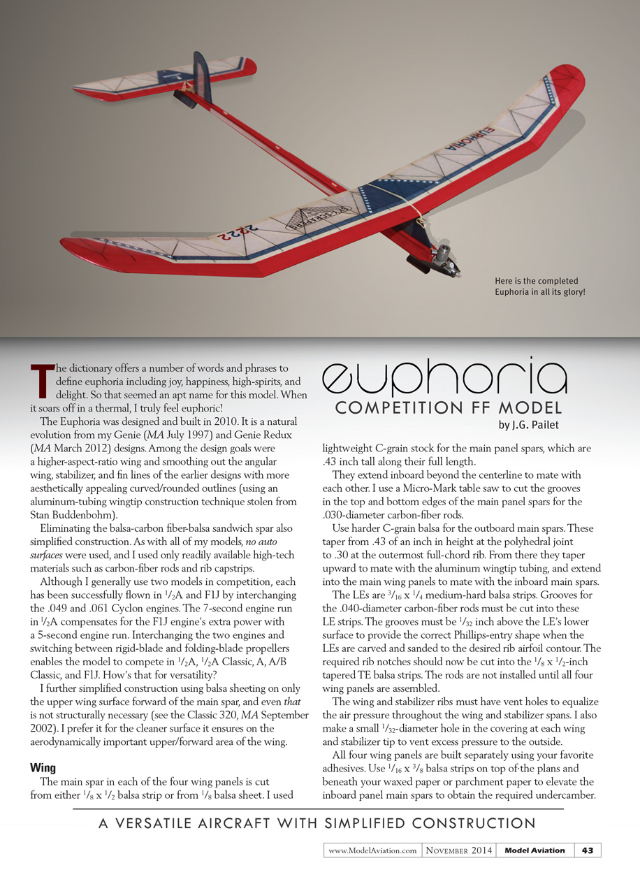
The dictionary offers a number of words and phrases to define euphoria including joy, happiness, high spirits, and delight. So that seemed an apt name for this model. When it soars off in a thermal, I truly feel euphoric!
The Euphoria was designed and built in 2010. It is a natural evolution from my Genie (MA July 1997) and Genie Redux (MA March 2012) designs. Among the design goals were a higher-aspect-ratio wing and smoothing out the angular wing, stabilizer, and fin lines of the earlier designs with more aesthetically appealing curved/rounded outlines (using an aluminum-tubing wingtip construction technique adopted from Stan Buddenbohm).
Eliminating the balsa–carbon-fiber–balsa sandwich spar also simplified construction. As with all of my models, no auto surfaces were used, and I used only readily available high-tech materials such as carbon-fiber rods and rib capstrips.
Although I generally use two models in competition, each has been successfully flown in 1/2A and F1J by interchanging the .049 and .061 Cyclon engines. The 7-second engine run in 1/2A compensates for the F1J engine’s extra power with a 5-second engine run. Interchanging the two engines and switching between rigid-blade and folding-blade propellers enables the model to compete in 1/2A, 1/2A Classic, A, A/B Classic, and F1J. How’s that for versatility?
I further simplified construction using balsa sheeting on only the upper wing surface forward of the main spar, and even that is not structurally necessary (see the Classic 320, MA September 2002). I prefer it for the cleaner surface it ensures on the aerodynamically important upper/forward area of the wing.
Wing
The main spar in each of the four wing panels is cut from either 1/8 x 1/2 balsa strip or from 1/8 balsa sheet. I used lightweight C-grain stock for the main panel spars, which are .43 inch tall along their full length. They extend inboard beyond the centerline to mate with each other. I use a Micro-Mark table saw to cut the grooves in the top and bottom edges of the main panel spars for the .030-inch-diameter carbon-fiber rods.
Use harder C-grain balsa for the outboard main spars. These taper from .43 inch in height at the polyhedral joint to .30 inch at the outermost full-chord rib. From there they taper upward to mate with the aluminum wingtip tubing, and extend into the main wing panels to mate with the inboard main spars.
The LEs are 3/16 x 1/4 medium-hard balsa strips. Grooves for the .040-inch-diameter carbon-fiber rods must be cut into these LE strips. The grooves must be 1/32 inch above the LE’s lower surface to provide the correct Phillips-entry shape when the LEs are carved and sanded to the desired rib airfoil contour.
The required rib notches should now be cut into the 1/8 x 1/2-inch tapered TE balsa strips. The rods are not installed until all four wing panels are assembled to each other.
The wing and stabilizer ribs must have vent holes to equalize the air pressure throughout the wing and stabilizer spans. I also make a small 1/32-inch-diameter hole in the covering at each wing and stabilizer tip to vent excess pressure to the outside.
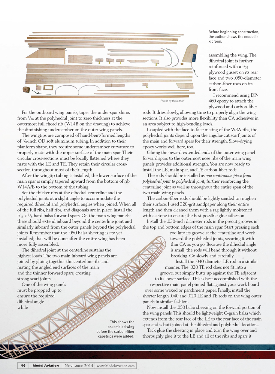
All four wing panels are built separately using your favorite adhesives. Use 1/16 x 3/8 balsa strips on top of the plans and beneath your waxed paper or parchment paper to elevate the inboard panel main spars to obtain the required undercamber. For the outboard wing panels, taper the under-spar shims from 1/16 at the polyhedral joint to zero thickness at the outermost full-chord rib (W14B on the drawing) to achieve the diminishing undercamber on the outer wing panels.
The wingtips are composed of hand-bent/formed lengths of 1/8-inch OD soft aluminum tubing. In addition to their planform shape, they require some undercamber curvature to properly mate with the upper surface of the main spar. Their circular cross-sections must be locally flattened where they mate with the LE and TE. They retain their circular cross-section throughout most of their length.
After the wingtip tubing is installed, the lower surface of the main spar is simply tapered upward from the bottom of rib W14A/B to the bottom of the tubing.
Set the thicker ribs at the dihedral centerline and set the polyhedral joints at a slight angle to accommodate the required dihedral and polyhedral angles when joined. When all of the full ribs, half ribs, and diagonals are in place, install the 1/16 x 1/8 hard balsa forward spars. On the main wing panels these should extend inboard beyond the centerline joint and similarly inboard from the outer panels beyond the polyhedral joints. Remember that the .050 balsa sheeting is not yet installed; that will be done after the entire wing has been more fully assembled.
The dihedral joint at the centerline sustains the highest loads. The two main inboard wing panels are joined by gluing together the centerline ribs and mating the angled end surfaces of the main and the thinner forward spars, creating strong scarf joints.
One of the wing panels must be propped up to ensure the required dihedral angle while assembling the wing. The dihedral joint is further reinforced with a 1/32 plywood gusset on its rear face and two .050-inch-diameter carbon-fiber rods on its front face.
I recommend using DP-460 epoxy to attach the plywood and carbon-fiber rods. It dries slowly, allowing time to properly align the wing sections. It also provides more flexibility than CA adhesives in an area subject to high-bending loads.
Coupled with the face-to-face mating of the W3A ribs, the polyhedral joints depend upon the angular-cut scarf joints of the main and forward spars for their strength. Slow-drying epoxy works well here, too.
Gluing the inward-extended ends of the outer wing panel forward spars to the outermost nose ribs of the main wing panels provides additional strength. You are now ready to install the LE, main spar, and TE carbon-fiber rods.
The rods should be installed as one continuous piece from polyhedral joint to polyhedral joint, further reinforcing the centerline joint as well as throughout the entire span of the two main wing panels.
The carbon-fiber rods should be lightly sanded to roughen their surface. I used 320-grit sandpaper along their entire length and then cleaned them with a rag lightly moistened with acetone to ensure the best possible glue adhesion.
Install the .030-inch-diameter rods in the precut grooves in the top and bottom edges of the main spar. Start pressing each rod into its groove at the centerline and work toward the polyhedral joints, securing it with thin CA as you go. Because the dihedral angle is small, the rods will bend through it without breaking. Go slowly and carefully.
Install the .040-inch-diameter LE rod in a similar manner. The .020-inch TE rod does not fit into a groove, but simply butts up against the TE adjacent to its lower surface. This is best accomplished with the respective main panel pinned flat against your work board over some waxed or parchment paper. Finally, install the shorter length .040 and .020 LE and TE rods on the wing outer panels in similar fashion.
Now install the .050 balsa sheeting on the forward portion of the wing panels. This should be lightweight C-grain balsa which extends from the rear face of the LE to the rear face of the main spar and is butt-jointed at the dihedral and polyhedral locations.
Tack glue the sheeting in place and turn the wing over and thoroughly glue it to the LE and all of the ribs and spars it contacts. The LE must be carved and sanded to its finished cross-sectional shape so that it blends into the full airfoil contour with the imbedded .040-inch-diameter rod, partially providing shape and damage protection.
The final wing construction step before covering is gluing the carbon-fiber capstrips in place on all ribs and diagonals. These capstrips should be .004 to .007 inch thick and 1/8 inch wide. Those on the top of the ribs must overlap the forward sheeting by at least 3/4 inch. Those on the bottom must overlap the LE by at least 3/32 inch and the TE by at least 1/4 inch. No capstrips are required on the underside of the short forward nose ribs. Lightly sand and clean the underside of the capstrips with acetone.
Horizontal Stabilizer
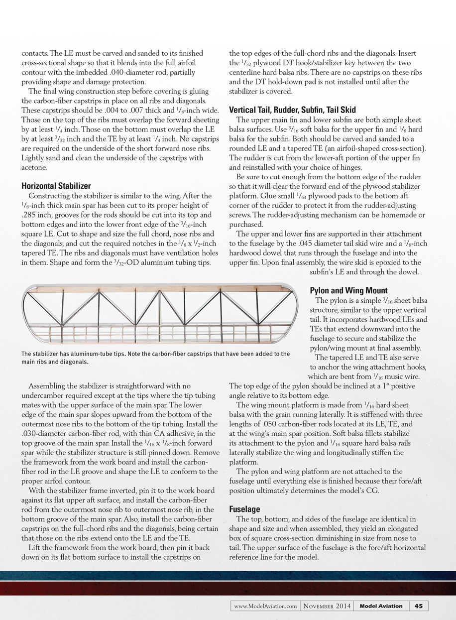
Constructing the stabilizer is similar to the wing. After the 1/8-inch-thick main spar has been cut to its proper height of .285 inch, grooves for the rods should be cut into its top and bottom edges and into the lower front edge of the 3/16-inch square LE. Cut to shape and size the full-chord nose ribs and the diagonals, and cut the required notches in the 1/8 x 1/2-inch tapered TE. The ribs and diagonals must have ventilation holes in them. Shape and form the 3/32-inch-OD aluminum tubing tips.
Assembling the stabilizer is straightforward with no undercamber required except at the tips where the tip tubing mates with the upper surface of the main spar. The lower edge of the main spar slopes upward from the bottom of the outermost nose ribs to the bottom of the tip tubing. Install the .030-inch-diameter carbon-fiber rod, with thin CA adhesive, in the top groove of the main spar. Install the 1/16 x 1/8-inch forward spar while the stabilizer structure is still pinned down. Remove the framework from the work board and install the carbon-fiber rod in the LE groove and shape the LE to conform to the proper airfoil contour.
With the stabilizer frame inverted, pin it to the work board against its flat upper aft surface, and install the carbon-fiber rod from the outermost nose rib to outermost nose rib in the bottom groove of the main spar. Also, install the carbon-fiber capstrips on the full-chord ribs and the diagonals, being certain that those on the ribs extend onto the LE and the TE.
Lift the framework from the work board, then pin it back down on its flat bottom surface to install the capstrips on the top edges of the full-chord ribs and the diagonals. Insert the 1/32-inch plywood DT hook/stabilizer key between the two centerline hard balsa ribs. There are no capstrips on these ribs and the DT hold-down pad is not installed until after the stabilizer is covered.
Vertical Tail, Rudder, Subfin, Tail Skid
The upper main fin and lower subfin are both simple sheet balsa surfaces. Use 3/16 soft balsa for the upper fin and 1/8 hard balsa for the subfin. Both should be carved and sanded to a rounded LE and a tapered TE (an airfoil-shaped cross-section). The rudder is cut from the lower-aft portion of the upper fin and reinstalled with your choice of hinges.
Be sure to cut enough from the bottom edge of the rudder so that it will clear the forward end of the plywood stabilizer platform. Glue small 1/64-inch plywood pads to the bottom aft corner of the rudder to protect it from the rudder-adjusting screws. The rudder-adjusting mechanism can be homemade or purchased.
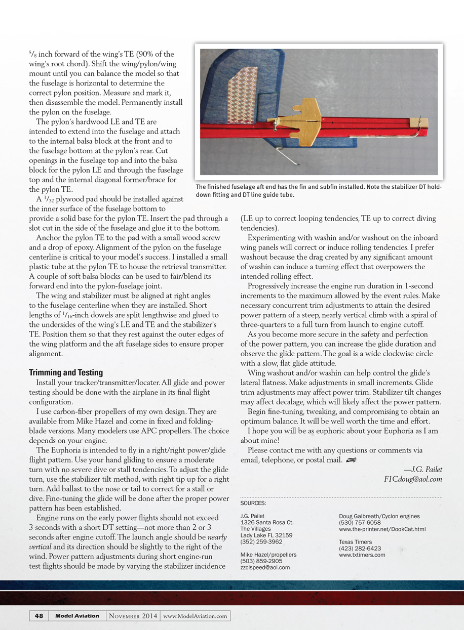
The upper and lower fins are supported in their attachment to the fuselage by the .045-inch-diameter tail skid wire and a 1/8-inch hardwood dowel that runs through the fuselage and into the upper fin. Upon final assembly, the wire skid is epoxied to the subfin's LE and through the dowel.
Pylon and Wing Mount
The pylon is a simple 3/16-inch sheet balsa structure, similar to the upper vertical tail. It incorporates hardwood LEs and TEs that extend downward into the fuselage to secure and stabilize the pylon/wing mount at final assembly.
The tapered LE and TE also serve to anchor the wing attachment hooks, which are bent from 1/16 music wire.
The top edge of the pylon should be inclined at a 1° positive angle relative to its bottom edge.
The wing mount platform is made from 1/16-inch hard sheet balsa with the grain running laterally. It is stiffened with three lengths of .050-inch carbon-fiber rods located at its LE, TE, and at the wing's main spar position. Soft balsa fillets stabilize its attachment to the pylon and 1/16 square hard balsa rails laterally stabilize the wing and longitudinally stiffen the platform.
The pylon and wing platform are not attached to the fuselage until everything else is finished because their fore/aft position ultimately determines the model's CG.
Fuselage
The top, bottom, and sides of the fuselage are identical in shape and size and when assembled, they yield an elongated box of square cross-section diminishing in size from nose to tail. The upper surface of the fuselage is the fore/aft horizontal reference line for the model.
The vertical formers are square 1/16 balsa with the grain diagonal in alternating directions. The same is true for the longer diagonal formers. All of the fuselage components are medium-weight, C-grain 1/16 balsa. Angular splice joints are required at the front to obtain the needed greater-than-36-inch lengths for the top, bottom, and side sheets.
The fuselage box is built with the corners open to permit the installation of the .050-inch carbon-fiber rods in each corner. A small balsa block with an internal 2-56 T-nut fills the aft end of the fuselage, providing a simple means of mounting ballast during flight testing and trimming.
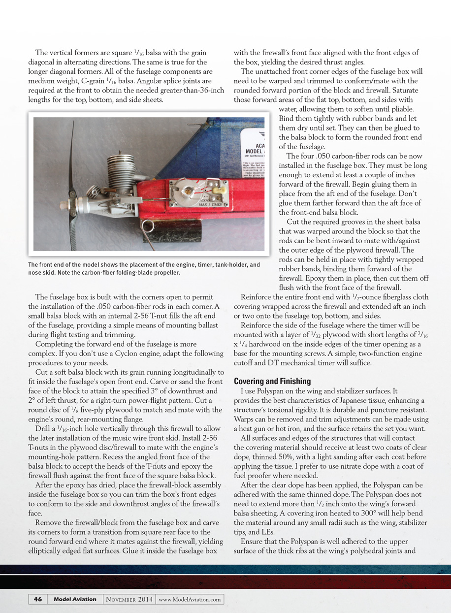
Completing the forward end of the fuselage is more complex. If you don’t use a Cyclon engine, adapt the following procedures to your needs.
Cut a soft balsa block with its grain running longitudinally to fit inside the fuselage’s open front end. Carve or sand the front face of the block to attain the specified 3° of downthrust and 2° of left thrust, for a right-turn power-flight pattern. Cut a round disc of 1/8-inch five-ply plywood to match and mate with the engine’s round, rear-mounting flange.
Drill a 1/16-inch hole vertically through this firewall to allow the later installation of the music wire front skid. Install 2-56 T-nuts in the plywood disc/firewall to mate with the engine’s mounting-hole pattern. Recess the angled front face of the balsa block to accept the heads of the T-nuts and epoxy the firewall flush against the front face of the square balsa block.
After the epoxy has dried, place the firewall–block assembly inside the fuselage box so you can trim the box’s front edges to conform to the side and downthrust angles of the firewall’s face.
Remove the firewall/block from the fuselage box and carve its corners to form a transition from square rear face to the round forward end where it mates against the firewall, yielding elliptically edged flat surfaces. Glue it inside the fuselage box with the firewall’s front face aligned with the front edges of the box, yielding the desired thrust angles.
The unattached front corner edges of the fuselage box will need to be warped and trimmed to conform/mate with the rounded forward portion of the block and firewall. Saturate those forward areas of the flat top, bottom, and sides with water, allowing them to soften until pliable. Bind them tightly with rubber bands and let them dry until set. They can then be glued to the balsa block to form the rounded front end of the fuselage.
The four .050-inch carbon-fiber rods can now be installed in the fuselage box. They must be long enough to extend at least a couple of inches forward of the firewall. Begin gluing them in place from the aft end of the fuselage. Don’t glue them farther forward than the aft face of the front-end balsa block.
Cut the required grooves in the sheet balsa that was warped around the block so that the rods can be bent inward to mate with/against the outer edge of the plywood firewall. The rods can be held in place with tightly wrapped rubber bands, binding them forward of the firewall. Epoxy them in place, then cut them off flush with the front face of the firewall.
Reinforce the entire front end with 1/2-ounce fiberglass cloth covering wrapped across the firewall and extended aft an inch or two onto the fuselage top, bottom, and sides.
Reinforce the side of the fuselage where the timer will be mounted with a layer of 1/32-inch plywood with short lengths of 3/16 x 1/4 hardwood on the inside edges of the timer opening as a base for the mounting screws. A simple, two-function engine cutoff and DT mechanical timer will suffice.
Covering and Finishing
I use Polyspan on the wing and stabilizer surfaces. It provides the best characteristics of Japanese tissue, enhancing a structure’s torsional rigidity. It is durable and puncture resistant. Warps can be removed and trim adjustments can be made using a heat gun or hot iron, and the surface retains the set you want.
All surfaces and edges of the structures that will contact the covering material should receive at least two coats of clear dope, thinned 50%, with a light sanding after each coat before applying the tissue. I prefer to use nitrate dope with a coat of fuel proofer where needed.
After the clear dope has been applied, the Polyspan can be adhered with the same thinned dope. The Polyspan does not need to extend more than 1/2 inch onto the wing’s forward balsa sheeting. A covering iron heated to 300° will help bend the material around any small radii such as the wing and stabilizer tips, and LEs.
Ensure that the Polyspan is well adhered to the upper surface of the thick ribs at the wing’s polyhedral joints and just inboard of the outermost wing ribs, and set the wing incidence to 0° relative to the stabilizer with the wing’s TE in line with the stabilizer’s TE. Use a temporary spacer under the tail to set the fuselage in level flight attitude.
I mounted the engine on the firewall and the remote fuel cutoff and propeller on the engine. Next, I located the pylon/wing-mount on the fuselage to attain the desired CG on the temporarily assembled model.
In addition to the engine, propeller, tank, timer, and stabilizer, simulate the weight of the tracker/locator transmitter and its holder tube by taping a 5-gram weight to the pylon’s TE before determining the pylon location.
Attach the wing to the top of the fuselage behind the engine with rubber bands. Fasten the stabilizer to the fuselage on the aft end. Now lay the inverted pylon/wing-mount platform, with dummy transmitter weight attached, on top of the wing with the TEs aligned.
Support the model under each side of the wing at a point just inboard of the outermost wing ribs and set the wing incidence and thrust angles as shown on the plans. Balance the model so the center of gravity is 5/8 inch forward of the wing's TE (90% of the wing's root chord). Shift the wing/pylon/wing mount until you can balance the model so that the fuselage is horizontal to determine the correct pylon position. Measure and mark it, then disassemble the model. Permanently install the pylon on the fuselage.
The pylon's hardwood LE and TE are intended to extend into the fuselage and attach to the internal balsa block at the front and to the fuselage bottom at the pylon's rear. Cut openings in the fuselage top and into the balsa block for the pylon LE and through the fuselage top and the internal diagonal former/brace for the pylon TE.
A 1/32-inch plywood pad should be installed against the inner surface of the fuselage bottom to provide a solid base for the pylon TE. Insert the pad through a slot cut in the side of the fuselage and glue it to the bottom.
Anchor the pylon TE to the pad with a small wood screw and a drop of epoxy. Alignment of the pylon on the fuselage centerline is critical to your model's success. I installed a small plastic tube at the pylon TE to house the retrieval transmitter. A couple of soft balsa blocks can be used to fair/blend its forward end into the pylon–fuselage joint.
The wing and stabilizer must be aligned at right angles to the fuselage centerline when they are installed. Short lengths of 1/16-inch dowels are split lengthwise and glued to the undersides of the wing's LE and TE and the stabilizer's TE. Position them so that they rest against the outer edges of the wing platform and the aft fuselage sides to ensure proper alignment.
Trimming and Testing
Install your tracker/transmitter/locator. All glide and power testing should be done with the airplane in its final flight configuration.
I use carbon-fiber propellers of my own design. They are available from Mike Hazel and come in fixed and folding-blade versions. Many modelers use APC propellers. The choice depends on your engine.
The Euphoria is intended to fly in a right/right power/glide flight pattern. Use your hand gliding to ensure a moderate turn with no severe dive or stall tendencies. To adjust the glide turn, use the stabilizer-tilt method, with right tip up for a right turn. Add ballast to the nose or tail to correct for a stall or dive. Fine-tuning the glide will be done after the proper power pattern has been established.
Engine runs on the early power flights should not exceed 3 seconds with a short DT setting—not more than 2 or 3 seconds after engine cutoff. The launch angle should be nearly vertical and its direction should be slightly to the right of the wind. Power pattern adjustments during short engine-run test flights should be made by varying the stabilizer incidence (LE up to correct looping tendencies, TE up to correct diving tendencies).
Experimenting with washin and/or washout on the inboard wing panels will correct or induce rolling tendencies. I prefer washout because the drag created by any significant amount of washin can induce a turning effect that overpowers the intended rolling effect.
Progressively increase the engine run duration in 1-second increments to the maximum allowed by the event rules. Make necessary concurrent trim adjustments to attain the desired power pattern of a steep, nearly vertical climb with a spiral of three-quarters to a full turn from launch to engine cutoff.
As you become more secure in the safety and perfection of the power pattern, you can increase the glide duration and observe the glide pattern. The goal is a wide clockwise circle with a slow, flat glide attitude.
Wing washout and/or washin can help control the glide's lateral flatness. Make adjustments in small increments. Glide-trim adjustments may affect power trim. Stabilizer-tilt changes may affect decalage, which will likely affect the power pattern.
Begin fine-tuning, tweaking, and compromising to obtain an optimum balance. It will be well worth the time and effort.
I hope you will be as euphoric about your Euphoria as I am about mine!
Please contact me with any questions or comments via email, telephone, or postal mail.
— J.G. Pailet [email protected]
SOURCES
- J.G. Pailet
1326 Santa Rosa Ct. The Villages Lady Lake, FL 32159 (352) 259-3962
- Mike Hazel — propellers
(503) 859-2095 [email protected]
- Doug Galbreath — Cyclon engines
(530) 757-6058 www.the-printer.net/DooCat.html
- Texas Timers
(423) 282-6423 www.txtimers.com
Transcribed from original scans by AI. Minor OCR errors may remain.

