
Exotic Rotors Heli
James M. Wang
Introduction
Bearingless main rotor heads are the coming technology for helicopters into the 1990s. Designing and testing a model bearingless rotor is a critical step in the development of functional and reliable systems for full-size applications. The model helicopter fraternity benefits from what’s learned. This article concludes a two-part series.
Last month’s article examined various rigid, hingeless, and bearingless model rotor head designs for RC model helicopters. This month we zoom in on a 6-ft.-dia. bearingless rotor currently being used for scientific research. By conducting wind-tunnel tests with this rotor system, we hope to advance our knowledge toward designing a successful bearingless rotor for future full-size helicopter applications.
The design emphasis for the 1990s is on developing a workable bearingless rotor because of the simplicity of the system: low parts count, aerodynamically clean, and no mechanical components to wear out. The beauty of the bearingless rotor system is that there are no mechanical bearings or hinges. Blade flapping, lead-lagging, and pitch change (feathering) are all accomplished by elastically bending or twisting the flexible rotor hub. The flexible part of the hub is called the flexbeam.
Bearingless rotors, however, are difficult to design properly. Avoiding aeroelastic and aeromechanical instability is a major challenge. Extensive theoretical and experimental research has gone into the development of bearingless rotors in the full-size helicopter industry during the last 10 years.
Aeroelastic vs. Aeromechanical Instability
Definitions and effects
- Aeroelastic (aerodynamic) instability: the main rotor blades may become unstable and begin flapping up and down wildly. If the pilot doesn’t correct for the instability immediately, the whole system can quickly disintegrate. Aeroelastic stability depends solely on main rotor and blade design.
- Aeromechanical stability: a function of the blade, rotor, and fuselage interacting as a whole. Air resonance and ground resonance are examples of aeromechanical instability; these resonances are extremely destructive.
Air resonance occurs when the rotor blade lead-lag frequency coalesces with one of the fuselage structural frequencies so that each oscillatory action excites the other, potentially leading to destruction. Ground resonance occurs while the helicopter is on the ground: if blade lead-lag frequency coincides with the natural frequency of the flexible landing gear, the machine can begin to rock laterally and be destroyed within seconds. Changing rotor rpm can often negate air and ground resonance quickly.
Design parameters affecting aeroelastic stability
Main rotor blades with chordwise center-of-gravity (CG) farther than 30% behind the leading edge are more prone to aeroelastic instability. If the chordwise CG is slightly forward of 25% (to coincide with the airfoil aerodynamic center), the system is likely to be aeroelastically stable.
Other parameters that may induce rotor aeroelastic instability:
- Too-soft rotor flap stiffness
- Blades that are torsionally too soft
- Too-soft control linkages
- Too much flexibility in cyclic or collective control setup
- Too-large blade radius or too-small chord
- Insufficient blade torsional inertia
Design engineers must examine these parameters more carefully for hingeless and bearingless rotors than for articulating or teetering rotors. Since flapping, lead-lagging, and feathering are achieved by deforming the rotor hub structure in hingeless and bearingless rotors, there are many structural couplings that may initiate unwanted control movements while the pilot is attempting to change only the pitch. Recent development of analysis technology for such strongly coupled structural systems has increased the popularity of hingeless and bearingless rotors.
Categories of Aeroelastic Instability
The two primary categories designers must consider are divergence and flutter.
Divergence
Divergence is static instability. In a poorly designed blade, divergence can occur in flight and cause the blade to snap off. Increasing the torsional stiffness of the blade system will prevent divergence and correct tendencies to flutter. Because modern rotor blades are already quite rigid, torsional stiffness is often increased by adding tension in the control linkage: using stiff pushrods, strong bellcranks, and avoiding long servo arms builds a slight amount of friction. Though friction can reduce control crispness, it helps aeroelastic stability.
Flutter
Flutter is a dynamic aeroelastic instability caused by interaction of aerodynamics with elastic and inertial forces. It is a self-sustained oscillation, different from resonance or forced-response oscillations. Two important types are pitch-flap flutter and flap-lag flutter.
- Pitch-flap flutter: similar to airplane wing flutter. As the blade flaps up, the leading edge twists upward, producing more lift and causing even more flapping. As it flaps down, the leading edge twists downward, reducing lift and causing more downward motion. Amplitude can increase until structural failure occurs—sometimes in seconds.
- Flap-lag flutter: peculiar to rotor blades. Blade flap motion and lead-lag motion are coupled through Coriolis forces and can be aggravated by negative aerodynamic damping. As the blade flaps up it will tend to lead forward; as it flaps down it will lag. Poor design can allow aerodynamic, elastic, and inertial forces to unite destructively.
Flutter is less common on RC models because their rotor blades and controls are generally stiffer than full-size blades. However, when certain conditions are present, flutter can still occur. On models the instability often appears as blades suddenly going wildly out of track by as much as five or six inches—some modelers call this phenomenon “woof.” Once triggered, bringing the model out of the critical operating sphere usually won’t stop the wild flapping; the pilot must either land immediately or try to pick a soft crash site.
Factors that promote flutter in RC helicopters
- High rpm
- Very lightweight blades
- Blade lead-lag which is too loose
- Flexible control rods or using outboard servo-arm horns
- Torsionally soft blades
- Chordwise CG forward of 20% or aft of 35%
- Aerodynamic perturbations (e.g., stalling blades in high-G maneuvers, sudden collective changes, maneuvers that distort rotor inflow)
Preventing Aeroelastic Instability in RC Models
The best ways to avoid pitch-flap and flap-lag instability:
- Select a forward location for the blade chordwise CG (23% to 27% ideal).
- Decrease blade aspect ratio (shorten rotor diameter).
- Tighten rotor head flap stiffness (compress rubber damper or O-ring).
- Add a Delta-3 flap hinge offset.
Delta-3 flap hinge offset (discussed in “Heli Flap Stabilizing Feedback,” Model Aviation, May 1989) prevents pitch-flap flutter and stabilizes the blade more than the helicopter as a whole. Examples: X-Cell uses Delta-3 on the tail rotor; GMP Legend’s flybarless head uses Delta-3 to reduce main rotor blade flapping and improve stability in gusts.
A lag-hinge offset known as Delta-4 prevents flap-lag flutter in full-size helicopters. Because mechanical lead-lag dampers are usually installed to damp lead-lag motion, Delta-4 is not often used on models. Rotor hubs with built-in coning angle may be less prone to flap-lag flutter, but that modification can be undesirable for pilots who like inverted flight.
Flutter may occur at any rotor thrust level and has been observed near 0° collective pitch on RC models. Non-rotating model blades in wind-tunnel tests have stalled at 0° angle of attack—possibly due to leading-edge flow separation. This separated flow generates unsteady aerodynamic forces that can excite wild blade flapping on model blades (lower Reynolds numbers due to small chord and low tip speed make this more likely on models).
Preventive measures for flow-induced instability:
- Weighted blades (increase centrifugal force to keep blade taut)
- Roughen the leading edge with coarse sandpaper (e.g., 100-grit) to increase effective Reynolds number and prevent flow separation
- Round or blunt the leading edge to reduce pitch-change sensitivity
- Slightly sand Hiller paddles to desensitize cyclic controls
The Bearingless Rotor Wind-Tunnel Program
The bearingless rotor featured here was originally designed by Boeing Helicopter Company for a future combat helicopter. The wind-tunnel model is an exact 1/6-scale replica of the proposed design.
Scaling down a full-size rotor for aerodynamic research is exacting and complicated. The stiffness, mass distribution, and inertia of the rotor blade, flexbeam, and pitch link must all be scaled using the Froude scaling law. RC model helicopter blades are usually much stiffer than what Froude scaling dictates, so models can perform maneuvers not possible for full-size helicopters.
The flexbeam and hub
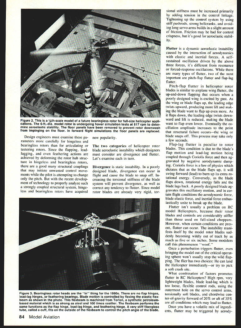
- The flexbeam: machined from Torlon (a synthetic petroleum-derived polymer), acts like flap, lead-lag, and feathering hinges.
- The cuff: a very stiff fiberglass tube fits on the outside of the flexbeam to control blade pitch; the pitch link attaches to the cuff.
Figure references in the tests:
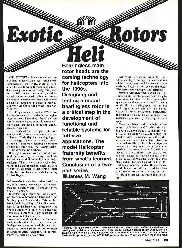
- Figure 1: floor plan of the Glenn L. Martin closed-return wind tunnel. Air is driven around the tunnel by a 2,000-hp electric motor with a seven-bladed fan (fan is about 15 ft. in diameter, repurposed B-29 propellers). Wind velocity in the test section can reach 300 mph.
- Figure 2: model bearingless rotor undergoing hover tests; floor panels removed to prevent rotor downwash impingement.
- Figure 3: flexibility of the elastic flexbeam.
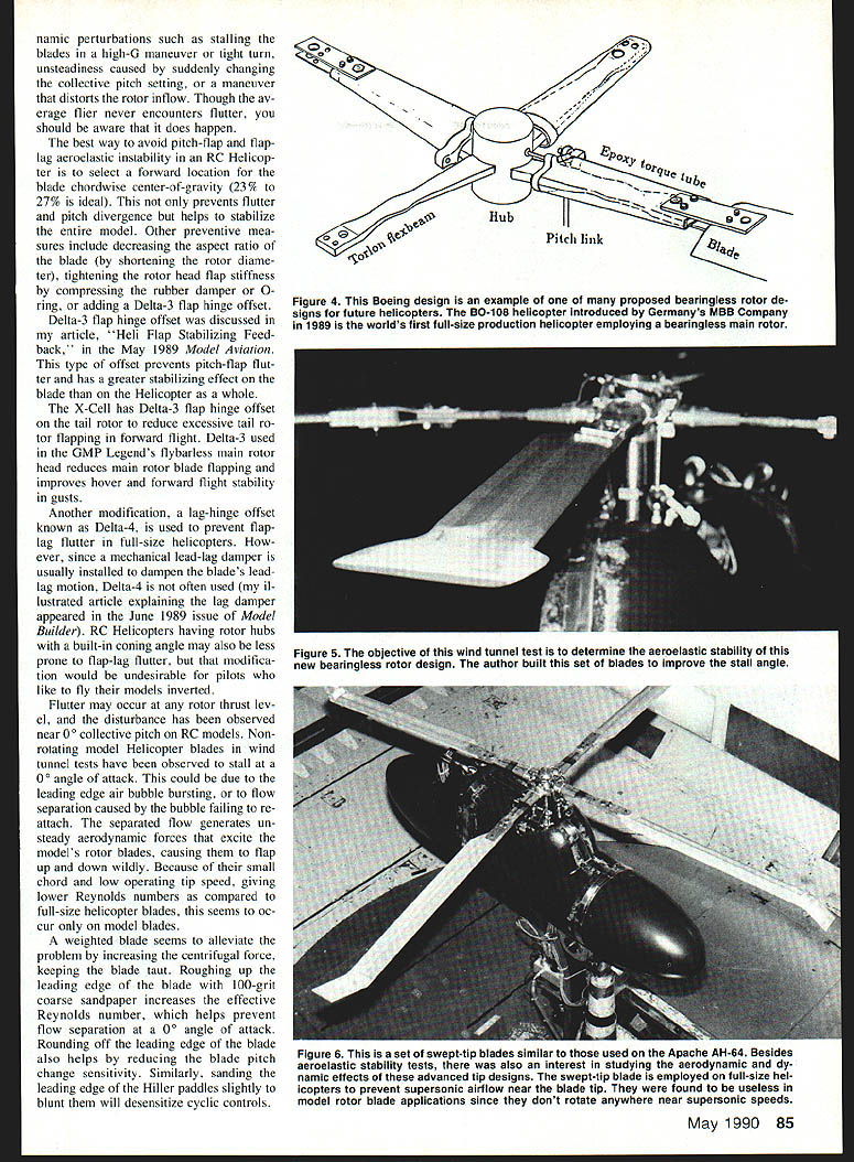
- Figure 4: rotor hub illustration.
- Figure 5: special set of blades built to improve stall angle.
- Figure 6: swept-tip blades similar to Apache AH-64; swept tips delay supersonic flow near full-size blade tips—useless on RC tips because they don’t approach supersonic speeds.
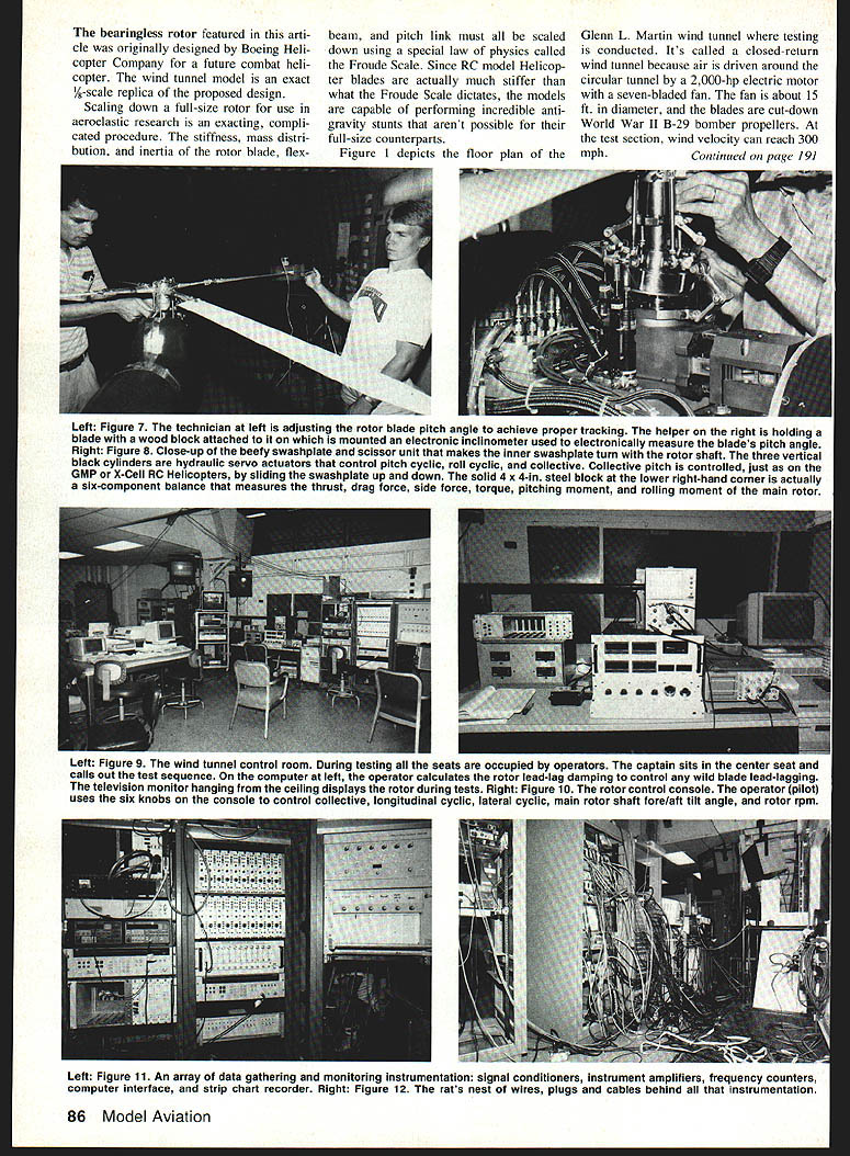
- Figure 7: measuring blade pitch angle on the 1/6-scale model using a wooden airfoil template with an electronic inclinometer.
- Figure 8: heavy swashplate and three hydraulic servo actuators for pitch cyclic, roll cyclic, and collective (collective controlled by sliding the swashplate up and down).
- Figure 9: control room and data-gathering devices; television monitor displays rotor during tests; safety barriers (1/4-in. steel plate on 1/2-in. plywood) protect the observation window.
- Figure 10: control console—no joystick; operator uses five knobs to adjust controls during tests.
- Figure 11: signal-processing equipment—signal conditioners, instrument amplifiers, frequency counters, computer interface, and strip-chart recorder.
- Figure 12: wiring behind instrumentation.
Test hardware and procedures
- The three control actuators are driven by hydraulic fluid; pumping fluid into either end moves the pistons inside the actuators (similar in principle to pneumatic retractable landing gear).
- A solid 4 x 4-in. steel block at the lower right is a six-component balance that measures thrust, drag, side force, torque, pitching moment, and rolling moment of the rotor; the balance costs approximately $20,000.
- The model rotor was tested at 817 rpm (most RC model helicopter rotors turn at 1,500 rpm or higher; pilots often stand within five to 15 ft. without protection, which concerns wind-tunnel engineers).
- The operator sets collective pitch, longitudinal cyclic, lateral cyclic, main rotor fore/aft shaft tilt angle, and rpm before tests.
Signals monitored (continuously recorded)
- Flapping angle
- Lead-lag angle
- Pitch angle of all blades
- Flexbeam bending and twisting strain
- Rotor pitching and rolling moments
- Thrust and drag forces
- Flap bending moment of blade number one
- Rotor rpm
A bank of data-gathering and recording devices records and plots these signals continuously on a strip-chart recorder. The control room operator calculates rotor lead-lag damping to ensure stable behavior. A ceiling television monitor displays the rotor during tests; if anything goes wrong, tunnel air velocity is shut down immediately and the rotor is stopped.
Conclusion
The wind-tunnel tests of this 1/6-scale bearingless rotor, and the valuable data collected, bring us closer to the goal of a better and safer helicopter for the 21st century. The phenomena observed and the insights gained will inform design choices for future full-size bearingless rotors and benefit the model helicopter community as well.
Transcribed from original scans by AI. Minor OCR errors may remain.

