
An Experiment in Drag Reduction
Les Garber
How important is drag reduction for small, electric-powered aircraft that fly at relatively slow velocities?
To answer that question, I ran 10 flight tests with two small flying wings. The results show a 17% decrease in the minimum power needed to sustain level flight. This drag reduction was a consequence of better streamlining and decreased frontal area (less flat-plate drag).
There are other benefits from less drag: higher maximum velocities, better aerobatic performance, and flatter glides.
The Wing Ding Design:
I've developed the Wing Ding design during the past two years and have built six different versions. Design is an iterative process for me; if a prototype has merit, I typically go on to build improved versions. The current basic design parameters are shown in Figure 1.
Because of the lightweight and low-drag design, Wing Dings are relatively fast, very aerobatic, and they easily handle 15 mph winds. All this performance comes from a geared 280 motor and less than 18 watts of power.
The eight 270 NiMH provide enough energy for more than six minutes of full-throttle aerobatic flight. With good charges, the models have made 21-minute flights at minimum throttle.
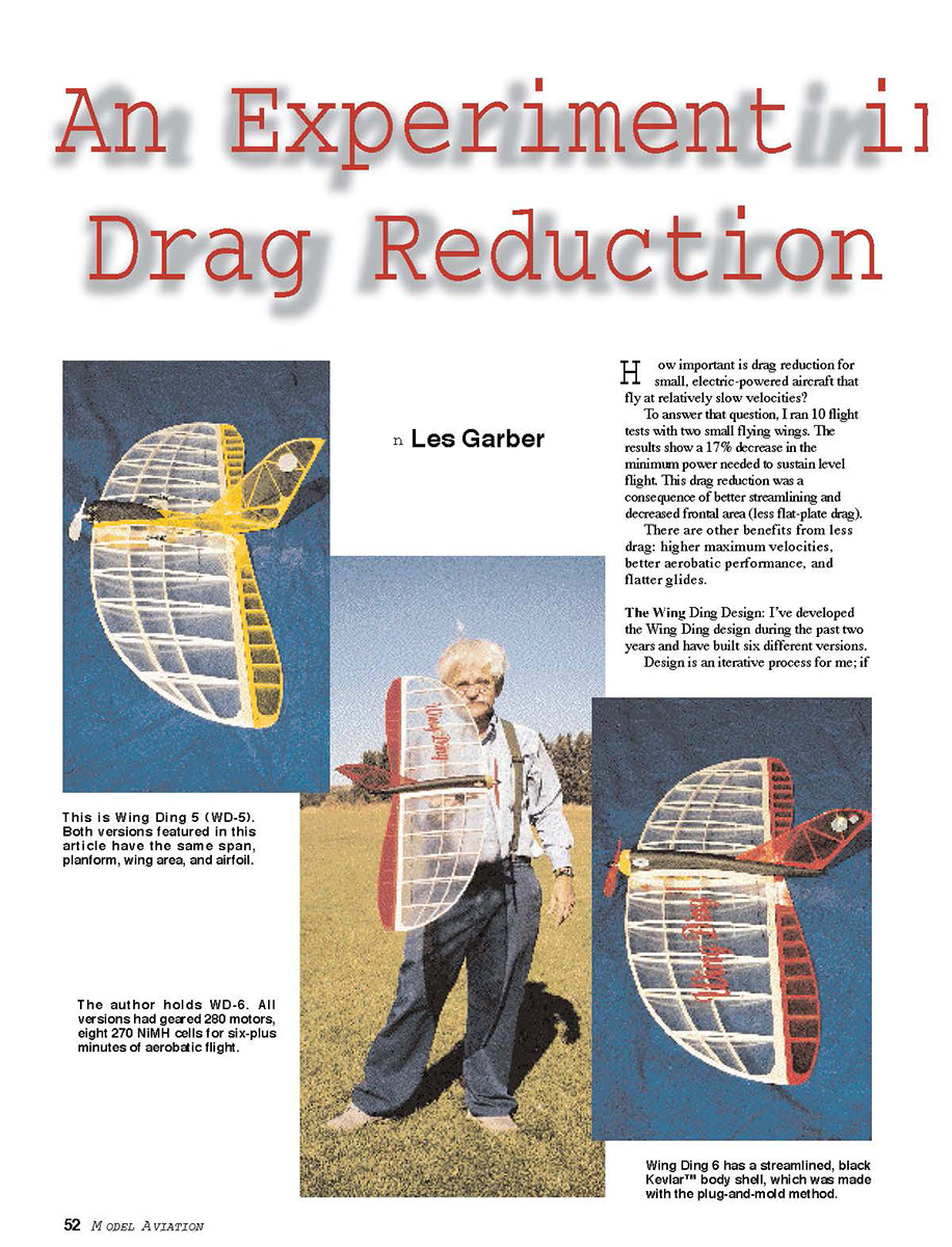
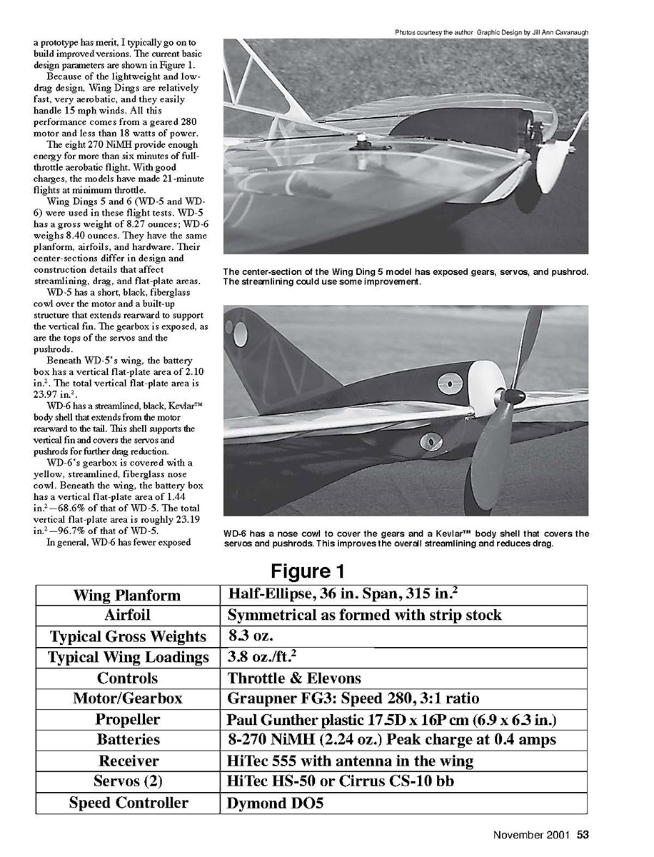
Wing Dings 5 and 6 (WD-5 and WD-6) were used in these flight tests. WD-5 has a gross weight of 8.27 ounces; WD-6 weighs 8.40 ounces. They have the same planform, airfoils, and hardware. Their center-sections differ in design and construction details that affect streamlining, drag, and flat-plate areas.
WD-5 has a short, black, fiberglass cowl over the motor and a built-up structure that extends rearward to support the vertical fin. The gearbox is exposed, as are the tops of the servos and the pushrods.
Beneath WD-5's wing, the battery box has a vertical flat-plate area of 2.10 in.2. The total vertical flat-plate area is 23.97 in.2.
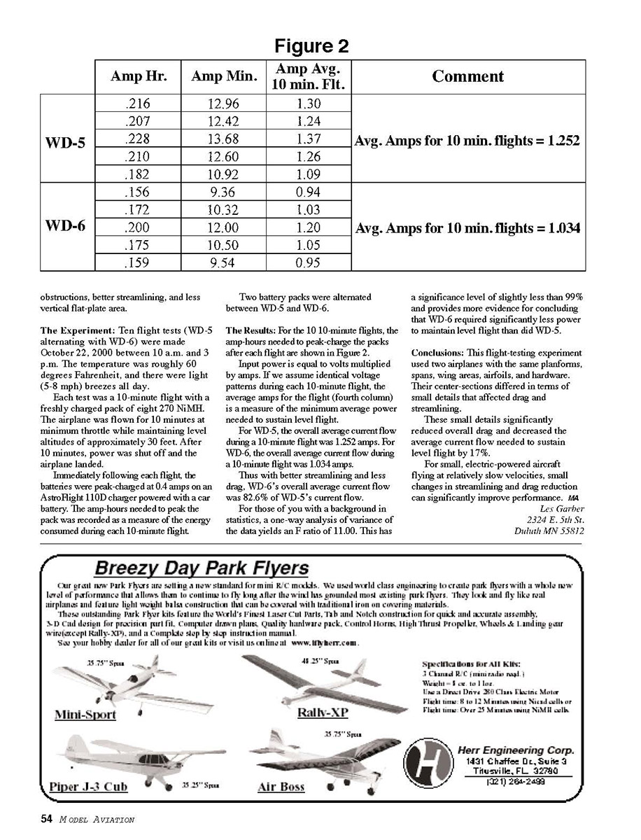
WD-6 has a streamlined, black, Kevlar™ body shell that extends from the motor rearward to the tail. This shell supports the vertical fin and covers the servos and pushrods for further drag reduction.
WD-6's gearbox is covered with a yellow, streamlined, fiberglass nose cowl. Beneath the wing, the battery box has a vertical flat-plate area of 1.44 in.2 — 68.6% of that of WD-5. The total vertical flat-plate area is roughly 23.19 in.2 — 96.7% of that of WD-5.
In general, WD-6 has fewer exposed obstructions, better streamlining, and less vertical flat-plate area.
Figure 1
- Wing Planform: Half-Ellipse, 36 in. Span, 315 in.2
- Airfoil: Symmetrical as formed with strip stock
- Typical Gross Weights: 8.3 oz.
- Typical Wing Loadings: 3.8 oz./ft.2
- Controls: Throttle & Elevons
- Motor/Gearbox: Graupner FG3: Speed 280, 3:1 ratio
- Propeller: Paul Gunther plastic 17.5D x 16P cm (6.9 x 6.3 in.)
- Batteries: 8-270 NiMH (2.24 oz.) Peak charge at 0.4 amps
- Receiver: HiTec 555 with antenna in the wing
- Servos (2): HiTec HS-50 or Cirrus CS-10 bb
- Speed Controller: Dymond D05
The Experiment:
Ten flight tests (WD-5 alternating with WD-6) were made October 22, 2000 between 10 a.m. and 3 p.m. The temperature was roughly 60 degrees Fahrenheit, and there were light (5-8 mph) breezes all day.
Each test was a 10-minute flight with a freshly charged pack of eight 270 NiMH. The airplane was flown for 10 minutes at minimum throttle while maintaining level altitudes of approximately 30 feet. After 10 minutes, power was shut off and the airplane landed.
Immediately following each flight, the batteries were peak-charged at 0.4 amps on an AstroFlight 110D charger powered with a car battery. The amp-hours needed to peak the pack was recorded as a measure of the energy consumed during each 10-minute flight.
Two battery packs were alternated between WD-5 and WD-6.
The Results:
For the 10 10-minute flights, the amp-hours needed to peak-charge the packs after each flight are shown in Figure 2.
Input power is equal to volts multiplied by amps. If we assume identical voltage patterns during each 10-minute flight, the average amps for the flight (fourth column) is a measure of the minimum average power needed to sustain level flight.
For WD-5, the overall average current flow during a 10-minute flight was 1.252 amps. For WD-6, the overall average current flow during a 10-minute flight was 1.034 amps.
Thus with better streamlining and less drag, WD-6's overall average current flow was 82.6% of WD-5's current flow.
For those of you with a background in statistics, a one-way analysis of variance of the data yields an F ratio of 11.00. This has a significance level of slightly less than 99% and provides more evidence for concluding that WD-6 required significantly less power to maintain level flight than did WD-5.
Conclusions:
This flight-testing experiment used two airplanes with the same planforms, spans, wing areas, airfoils, and hardware. Their center-sections differed in terms of small details that affected drag and streamlining.
These small details significantly reduced overall drag and decreased the average current flow needed to sustain level flight by 17%.
For small, electric-powered aircraft flying at relatively slow velocities, small changes in streamlining and drag reduction can significantly improve performance.
Les Garber 2324 E. 5th St. Duluth MN 55812
Transcribed from original scans by AI. Minor OCR errors may remain.

