
F-86D Sabre
The North American F-86D Sabre, the Northrop F-89 Scorpion, and the Lockheed F-94 Starfire were the mainstays of the Air Defense Command’s fighter-interceptor force during the 1950s. The F-86 filled the bulk of the Air Defense Command role, serving in 20 of the 30 wings that made up the force. It continued to serve into the mid-1960s with the Air National Guard (ANG) as more modern equipment replaced it in the U.S. Air Force.
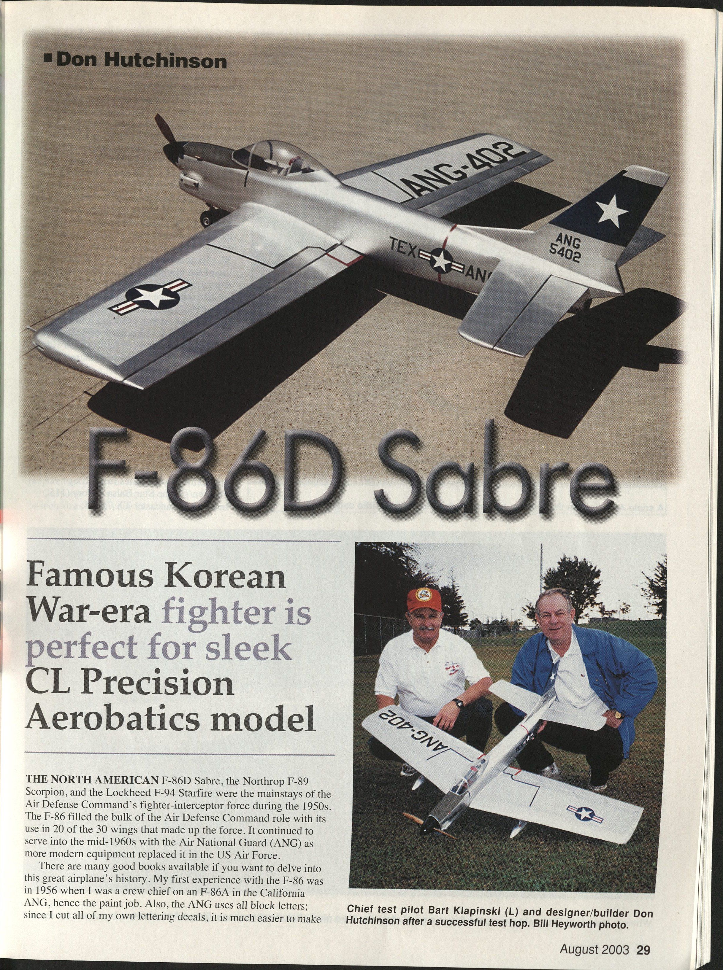
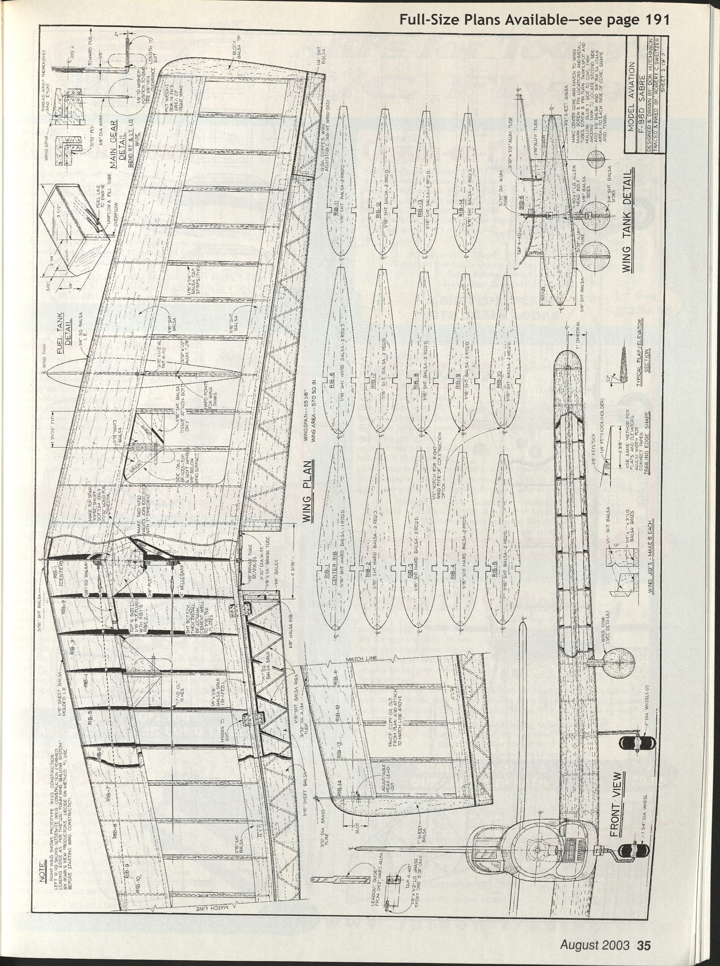
There are many good books available if you want to delve into this airplane’s history. My first experience with the F-86 was in 1956 when I was a crew chief on an F-86A in the California ANG, hence the paint job. The ANG uses all block letters; since I cut all of my own lettering decals, it is much easier to make this style with no curved lines.
We fly a P-40 event (for any profile model, with a .40 maximum engine size) in Texas, so my strategy was to design an F-86A with a Fox .35 up front. It flew so well that I decided to do a full-fuselage version, and the F-86D was the natural choice with that big spinner on the nose simulating the radome. You also get a little more propeller clearance with the higher thrust line.
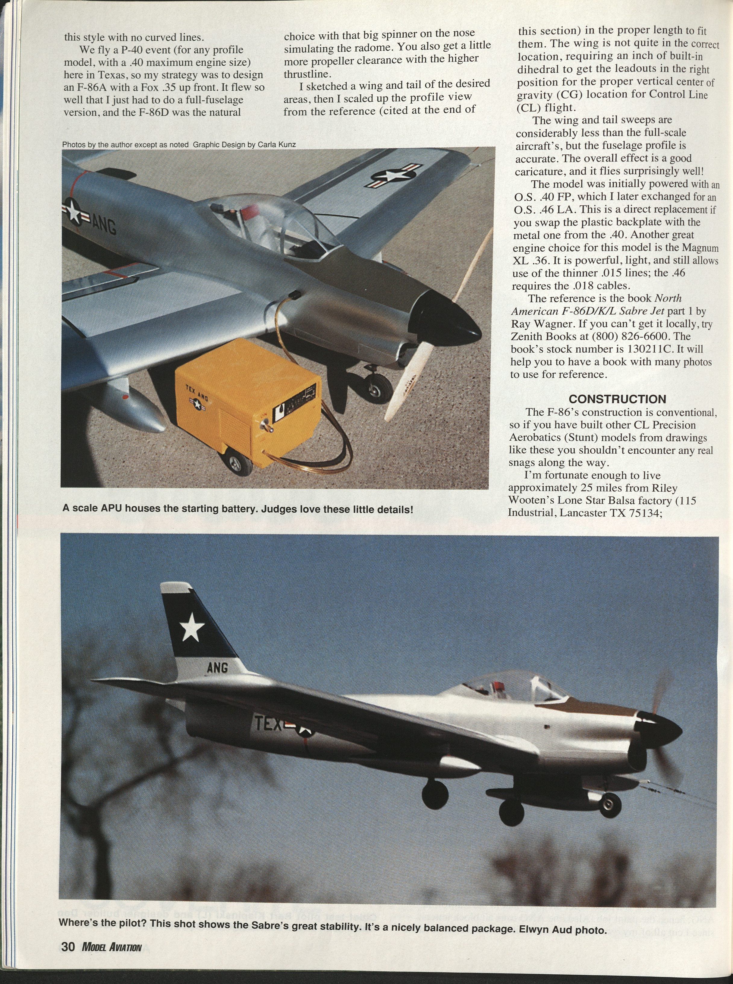
I sketched a wing and tail of the desired areas, then scaled up the profile view from the reference (see below) to the correct length to fit them. The wing is not quite in the correct location on the model, requiring an inch of built-in dihedral to get the leadouts in the right position for the proper vertical center of gravity (CG) location for Control Line (CL) flight. The wing and tail sweeps are considerably less than the full-scale aircraft’s, but the fuselage profile is accurate. The overall effect is a good caricature, and it flies surprisingly well!
The model was initially powered with an O.S. .40 FP, which I later exchanged for an O.S. .46 LA. This is a direct replacement if you swap the plastic backplate with the metal one from the .40. Another great engine choice for this model is the Magnum XL .36: it is powerful, light, and still allows use of the thinner .015 lines; the .46 requires the .018 cables.
Reference: North American F-86D/K/L Sabre Jet part 1 by Ray Wagner. If you can’t get it locally, try Zenith Books at (800) 826-6600. The book’s stock number is 130211C. It helps to have a book with many photos for reference.
CONSTRUCTION
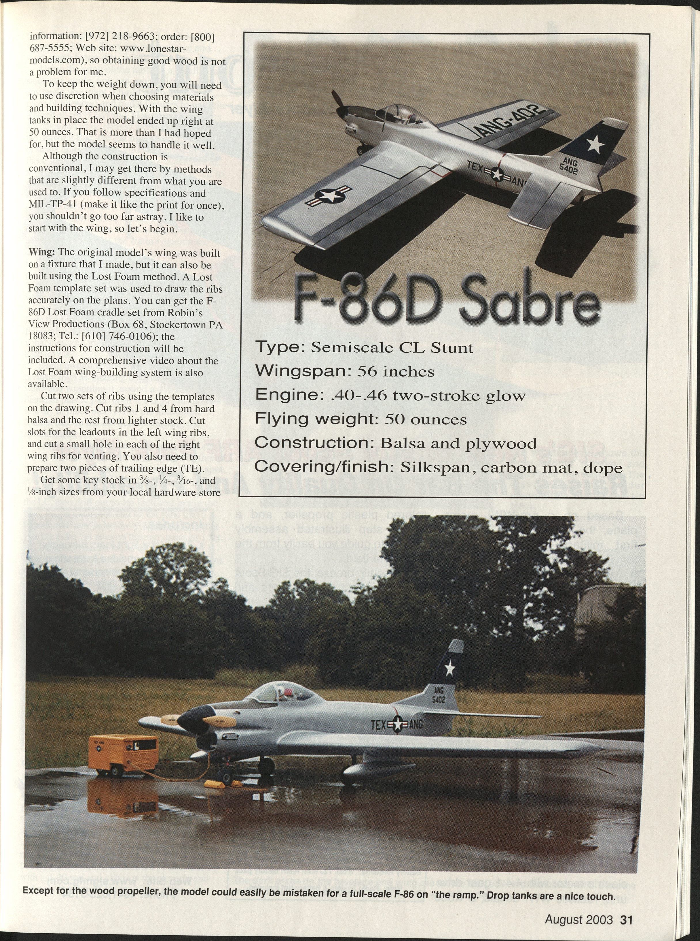
The F-86’s construction is conventional, so if you have built other CL Precision Aerobatics (Stunt) models from drawings like these, you shouldn’t encounter any real snags. To keep the weight down, use discretion when choosing materials and building techniques. With the wing tanks in place, the model ended up right at 50 ounces. That is more than I had hoped for, but the model handles it well.
I follow specifications and MIL-TP-41 where practical. I also have the advantage of being close to a good balsa supplier, but you can source suitable wood from hobby suppliers.
Wing
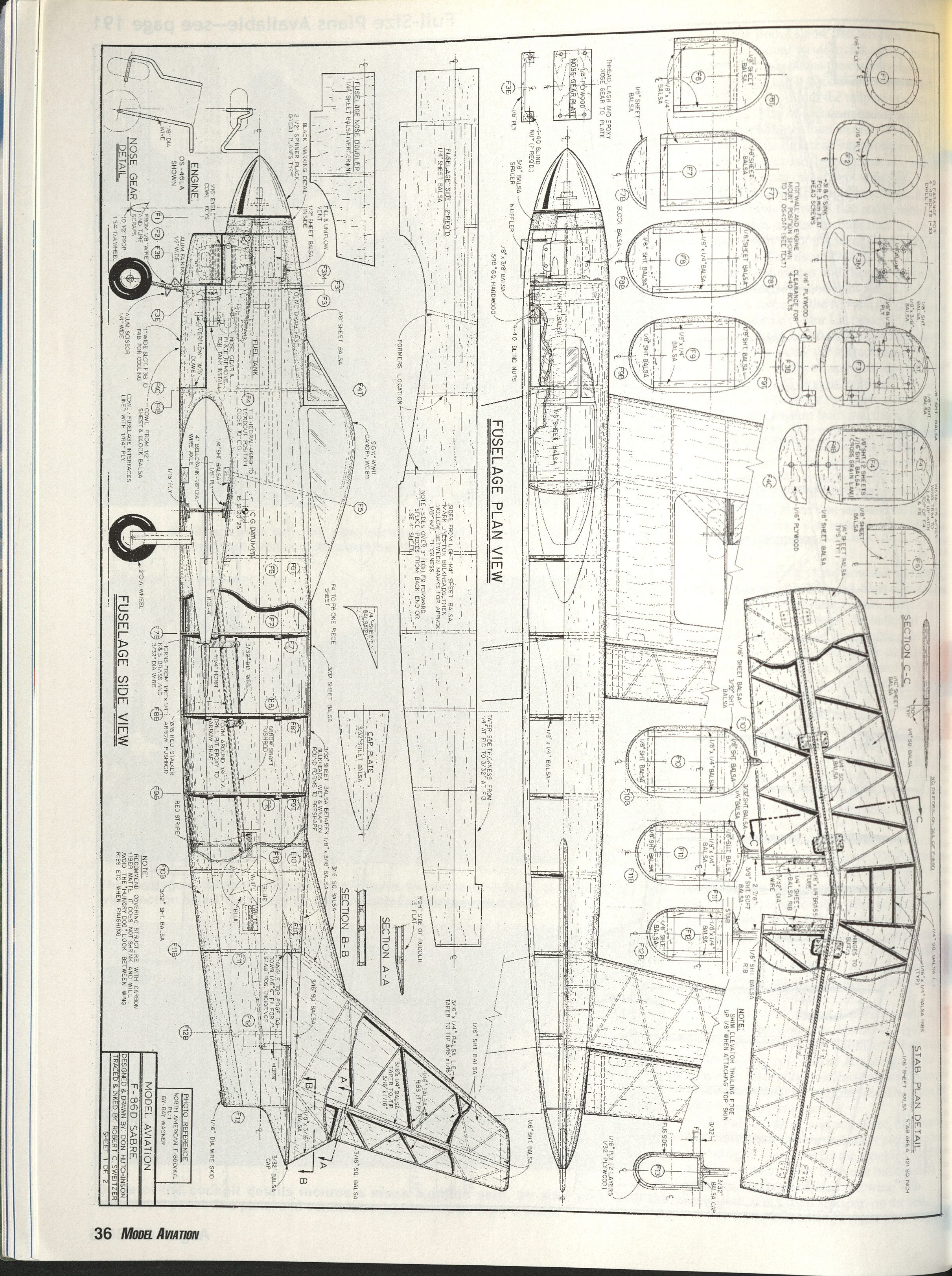
- The original model’s wing was built on a fixture I made, but it can also be built using the Lost Foam method. A Lost Foam template set was used to draw the ribs accurately on the plans. You can get the F-86D Lost Foam cradle set from Robin’s View Productions (Box 68, Stockertown PA 18083; Tel.: [610] 746-0106); instructions for construction are included. A comprehensive video about the Lost Foam wing-building system is also available.
- Cut two sets of ribs using the templates on the drawing. Cut ribs 1 and 4 from hard balsa and the rest from lighter stock. Cut slots for the leadouts in the left wing ribs, and cut a small hole in each of the right wing ribs for venting. Prepare two pieces of trailing edge (TE).
- Get some key stock in 3/8-, 1/4-, 3/16-, and 1/8-inch sizes (12-inch-long square steel bars) from your local hardware store for shaping; they work much better than wire.
- Use the edge of a table or smaller stock as a sanding guide to get any angle you want. I build my wings on a piece of plywood and make fixtures to hold the leading edges (LEs) and TEs. The TE fixtures are pinned along the TE line on the drawing; the LE in its fixtures floats until you start gluing the ribs.
- Place square blocks on the wing centerline to act as stops for the LEs and TEs. Pin the TE to the fixtures and put the LE close to the right spot.
- Use a rib-spacing fixture (looks like the bottom half of a shoe box with the sides removed) to position and tack-glue the ribs sequentially from the center out to the tip. The fixture keeps the ribs accurately spaced and vertical.
- Install the top spar, remove the wing from the fixtures, then install the lower spar and finish-glue all joints. Build the other wing, then join them with an inch of dihedral at each tip rib.
- Begin installing all sheeting. I pre-form my LE sheeting by soaking it with water and wrapping it around a 4-1/2-inch-diameter plastic pipe until dry. This allows it to lay in place nicely. Put the aluminum leadout tube in the LE before sheeting the second surface.
- Mock up the leadout guide and temporarily install the bellcrank, then run a piece of thread through the guide and over the wing to the spot where the tube will exit. Use a piece of sharpened 1/16-inch wire through the tip mock-up to pierce the LE, then drill out to 3/32 inch and install the tube. Angle the inside end of the tube like a hypodermic needle so you can poke the leadout through it easier later.
- Ensure the plywood bellcrank mounts are flush with the edges of the ribs so the 1/16-inch center-section sheeting can be glued well. The bellcrank with leadouts and pushrod assembly is installed before closing the top center-section sheeting.
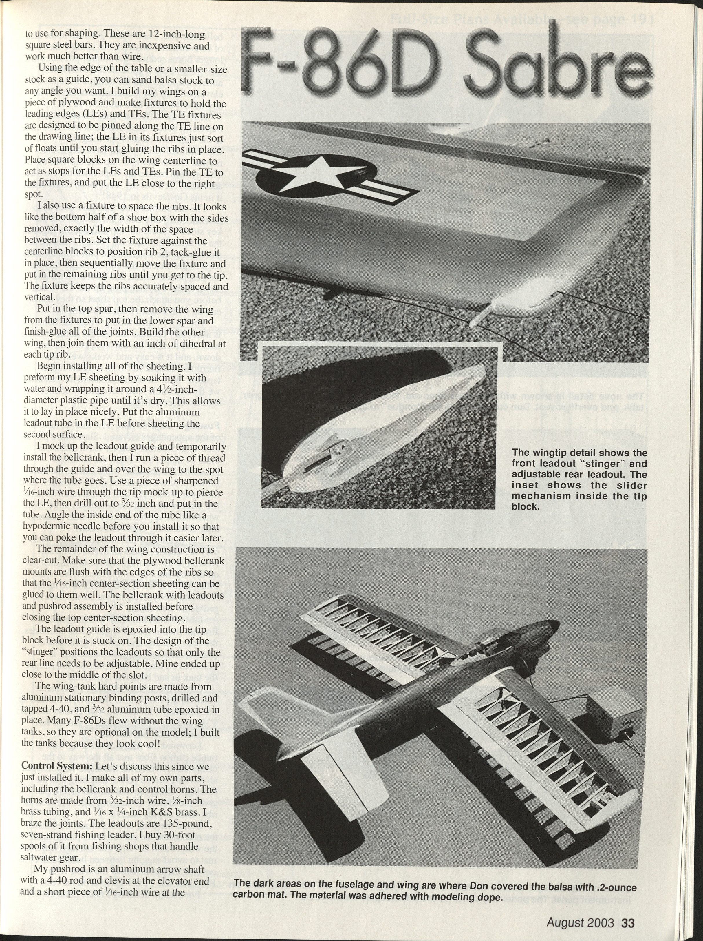
- The leadout guide is epoxied into the tip block before it is glued on. The design of the "stinger" positions the leadouts so only the rear line needs to be adjustable. Mine ended up close to the middle of the slot.
- Wing-tank hard points are made from aluminum stationary binding posts, drilled and tapped 4-40, with 3/32 aluminum tube epoxied in place. Many F-86Ds flew without the wing tanks, so they are optional on the model; I built them because they look cool!
Control System
- I make my own parts, including the bellcrank and control horns. The horns are made from 3/32-inch wire, 1/8-inch brass tubing, and 1/16 x 1/4-inch K&S brass; I braze the joints.
- The leadouts are 135-pound, seven-strand fishing leader purchased on 30-foot spools from saltwater tackle shops.
- My pushrod is an aluminum arrow shaft with a 4-40 rod and clevis at the elevator end and a short piece of 1/16-inch wire at the bellcrank/servo end.
- I know this flies in the face of conventional wisdom, but using 1-inch and longer horns reduces control pressures to a safe point. I use a good steel clevis, which allows me to reach into the tailpipe to adjust the elevators. I do not recommend doing this on any model bigger than an O.S. .40 FP.
- Because the bellcrank axle is close to the flap horn on a swept wing, a conventional setup would have larger-than-normal errors between flap and elevator travel. The system used here makes the flaps track the elevators accurately. This isn’t my idea—Bob Palmer used it in his Go-Devils in 1948.
- Tail surfaces and flaps are built up for rigidity and light weight. Use key stock to bevel the top and bottom edges of the 1/4-square elevator leading-edge pieces. Lay out the LE, bottom sheet, and ribs; sand the ribs down to the TE, then prop up the TE 1/8 inch before attaching the top sheet to avoid wash-in.
- Use 1/8 x 1/4-inch tubing where the horns go because the control horns undulate as the surfaces move up and down; this solution is simple and effective.
- The fin/rudder is built flat with only the rudder tapered. Given the large area and circular flight, you have plenty of effective rudder offset in flight.
Fuselage
- Start with a pair of 4- to 5-pound-density balsa sides. Cut to shape and mark bulkhead locations. Be accurate when cutting the sides to ensure the stabilizer has the correct positive incidence. Sand the taper toward the tail, then carefully hollow the insides between the bulkheads aft of F5 to approximately 1/8-inch thickness after final contouring.
- Glue in 1/16-inch hard-balsa doublers. While they cure, make all bulkheads. Assemble the fuselage upside-down, then add the top and bottom bulkheads. The small sheet pieces and blocks for the front end are typical and straightforward.
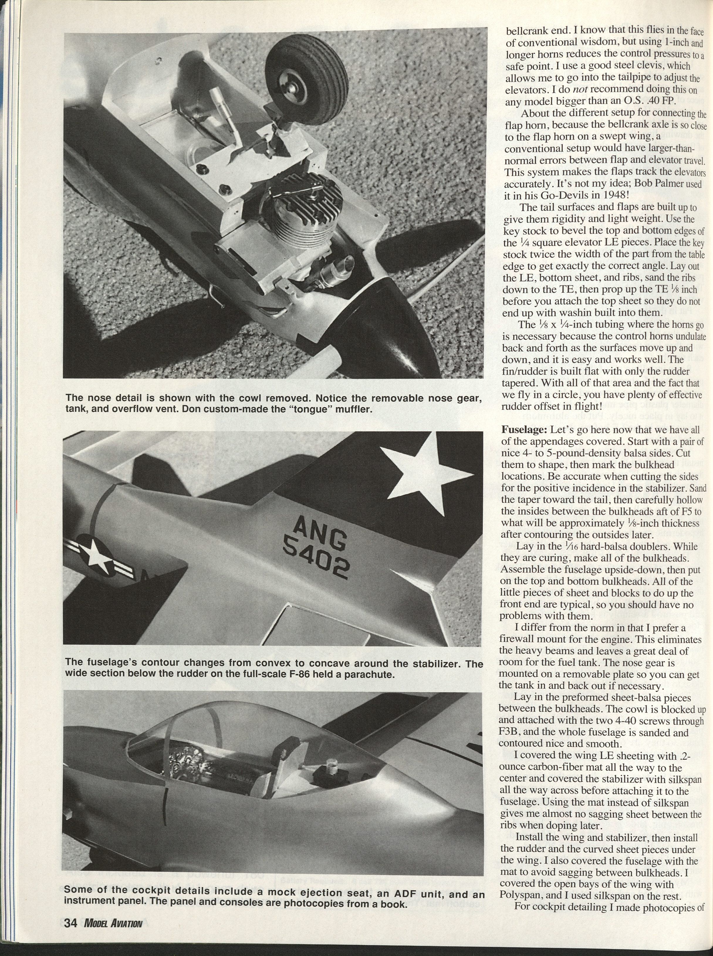
- I prefer a firewall mount for the engine. This eliminates heavy beams and leaves room for the fuel tank. The nose gear is mounted on a removable plate so you can remove the tank if necessary.
- Fit pre-formed sheet-balsa pieces between the bulkheads. The cowl is blocked up and attached with two 4-40 screws through F3B, then sand and contour the fuselage smooth.
- I covered the wing LE sheeting with 0.2-ounce carbon-fiber mat all the way to the center and covered the stabilizer with silkspan before attaching it to the fuselage. Using mat instead of silkspan minimizes sagging between ribs when doping later.
- Install wing and stabilizer, then install rudder and curved sheet pieces under the wing. I also covered the fuselage with mat to avoid sagging between bulkheads. I covered the open bays of the wing with Polyspan and used silkspan on the rest.
- For cockpit detailing I photocopied the instrument panel and side consoles from the reference book. I made a simple ejection seat and a dummy ADF unit and cabin-pressurization regulator mounted behind the seat. The Sig WC 811 canopy is an ideal fit.
- I recommend mixing epoxy and microballoons for fillets. The full-scale aircraft didn't have fillets at the wing/fuselage joint, so keep these fillets to a small radius. Filleting at the stabilizer/rudder location flows from concave to convex—check photos in the reference to get this area realistic.
Plans/diagrams included in the original publication (full-size plans and details):
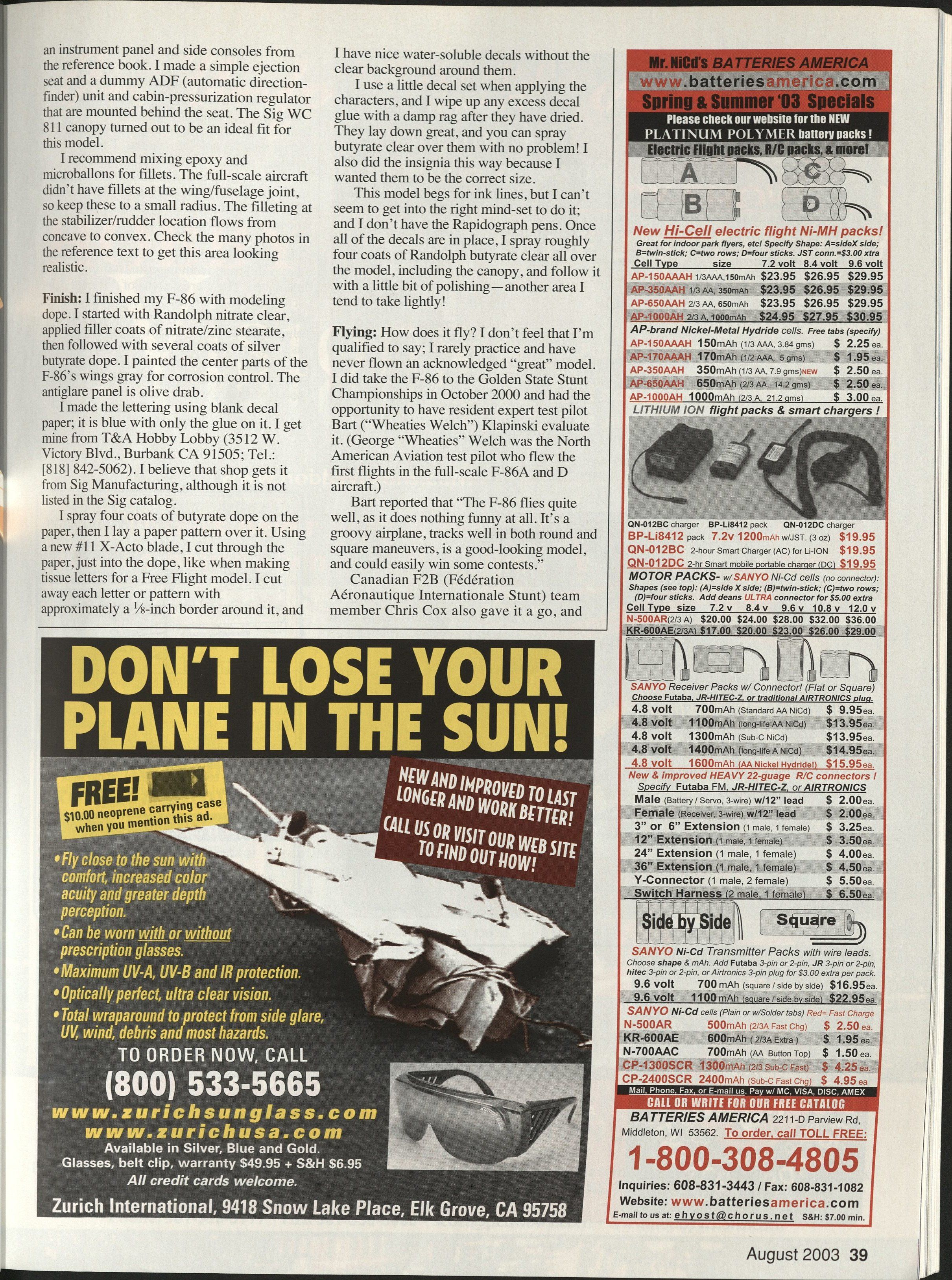
- Fuselage side view
- Fuselage plan view
- Nose gear detail
- Engine
- Section A-A
- Section B-B
- Section C-C
- Stab plan detail
Finish
- I finished my F-86 with modeling dope: start with Randolph nitrate clear, apply filler coats of nitrate/zinc stearate, then several coats of silver butyrate dope. Paint the center parts of the wings gray for corrosion control. The antiglare panel is olive drab.
- Lettering: I made the lettering using blank decal paper (blue on one side with adhesive). I get it from T&A Hobby Lobby (3512 W. Victory Blvd., Burbank CA 91505; Tel.: [818] 842-5062). Spray four coats of butyrate dope on the paper, lay a paper pattern over it, and cut each letter with a new #11 X-Acto blade, cutting just into the dope. Cut away each letter or pattern with approximately a 1/8-inch border. This yields water-soluble decals without a clear background.
- Use a little decal set when applying characters, and wipe up any excess decal glue with a damp rag after they dry. Spray about four coats of Randolph butyrate clear over the model, including the canopy, then do a little polishing.
I considered adding ink panel lines but did not—Rapidograph pens would be useful for that. I also made the insignia as decals to be the correct size.
Flying
How does it fly? I rarely practice and have never flown an acknowledged “great” model, but I did take the F-86 to the Golden State Stunt Championships in October 2000. Resident expert test pilot Bart ("Wheaties Welch") Klapinski evaluated it (George "Wheaties" Welch was the North American Aviation test pilot who flew the first flights in the full-scale F-86A and D aircraft). Bart reported:
- "The F-86 flies quite well, as it does nothing funny at all. It's a groovy airplane, tracks well in both round and square maneuvers, is a good-looking model, and could easily win some contests."
Canadian F2B team member Chris Cox also flew it and said:
- "Ease of making round maneuvers round. I have flown many high-end competition models that would not do as nice a round maneuver. All in all, an absolute joy to fly! More than capable of winning. The only advice I need to give is hold some down-elevator to keep the nose wheel on the ground until the model is about ready to lift off. This will keep the nose from turning in on you as the model is released."
The F-86D builds into a nice-looking model that differs from the usual "Stunt machine." There are dozens of paint schemes to choose from. If you make a dummy APU that plugs into the side of the fuselage for starting and have former Air Force personnel as judges, you can have a lot of fun with your Sabre—and maybe even win some hardware.
Don Hutchinson 4 Mistywood Ct. Mansfield, TX 76063
Transcribed from original scans by AI. Minor OCR errors may remain.

