
F6F Hellcat Profile Carrier
Frank Kelly
The 1979 Nationals winner explains design principles and design development. Way to go . . .
This model is the result of over five years of development, through three sets of AMA rules for Profile Navy Carrier. It took first place at the 1979 Nats in Lincoln with an out-of-the-box stock engine, winning out over a large entry of skillful competitors, many of whom had expensive custom engines. The basic design has been built as a TBF Avenger and SNJ Texan as well as the F6F Hellcat by my friends and me.
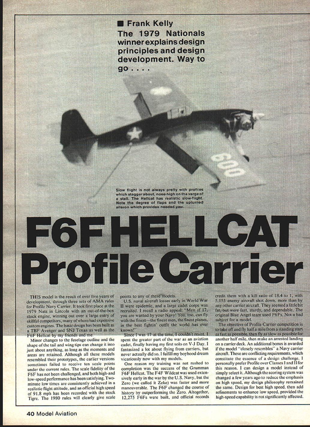
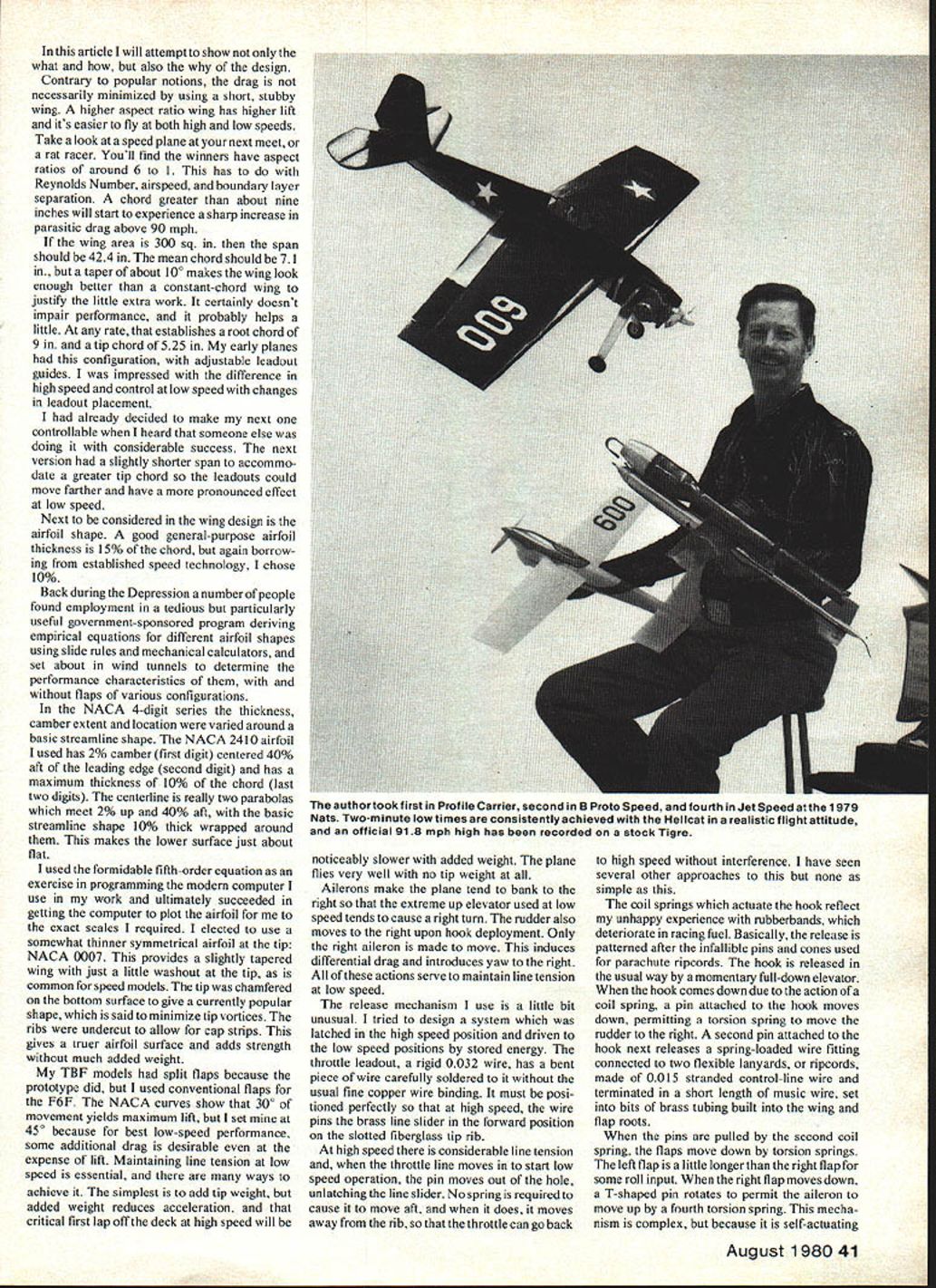
Minor changes to the fuselage outline and the shape of the tail and wing tips can change it into just about anything, as long as the moments and areas are retained. Although all these models resembled their prototypes, the earlier versions sometimes failed to receive ten scale points under the current rules. The scale fidelity of the F6F has not been challenged, and both high- and low-speed performance has been satisfying. Two-minute low times are consistently achieved in a realistic flight attitude, and an official high speed of 91.8 mph has been recorded with the stock Tigre. The 1980 rules will clearly give scale points to any of these models.
U.S. naval aircraft losses early in World War II were epidemic, and a large cadet corps was recruited. I recall a radio appeal: "Men of 17, you are wanted by your Navy! You, too, can fly with the finest—the finest men, the finest planes, in the best fighting outfit the world has ever known!"
Since I was 17 at the time, I couldn't resist. I spent the greater part of the war as an aviation cadet, finally having my first solo on V-J Day. I fantasized a lot about flying from carriers, but never actually did so. I fulfill my boyhood dream vicariously now with my models.
One reason my training was not rushed to completion was the success of the Grumman F6F Hellcat. The F4F Wildcat was used extensively early in the war by the U.S. Navy, but the Zero (we called it Zeke) was faster and more maneuverable. The F6F changed the course of history by outperforming the Zero. Altogether, 12,275 F6Fs were built, and official records credit them with a kill ratio of 18.4 to 1, with 5,155 enemy aircraft shot down, more than by any other carrier aircraft. They seemed a little bit fat, but were fast, sturdy, and dependable. The original Blue Angel team used F6Fs. Not a bad subject for a model.
The objective of Profile Carrier competition is to take off and fly half a mile from a standing start as fast as possible, then fly as slow as possible for another half mile, then make an arrested landing on a carrier deck. An additional bonus is awarded if the model "closely resembles" a Navy carrier aircraft. These are conflicting requirements, which constitute the essence of a design challenge. I personally prefer Profile over Classes I and II for this reason. I can design a model instead of simply select it. Although the scoring system was changed a few years ago to reduce the emphasis on high speed, my design philosophy remained the same: design for best high-speed, then add refinements to enhance low speed, provided the high-speed capability is not significantly affected.
Contrary to popular notions, drag is not necessarily minimized by using a short, stubby wing. A higher aspect-ratio wing has higher lift and is easier to fly at both high and low speeds. Take a look at the speed plane next to the rat racer. You'll find winners have aspect ratios around 6:1. If wing area is 300 sq. in., span should be about 42.4 in.; the mean chord should be about 7.1 in. A taper of about 10% makes the wing look enough better; a constant-chord wing justifies little extra work, certainly doesn't impair performance and probably helps a little. This rate establishes a root chord of about 9 in. and a tip chord of about 5.25 in.
Early planes had adjustable leadout guides. I'm impressed at the difference in high-speed control and low-speed changes that leadout placement can make. Once the leadouts are decided, make them controllable. I heard someone else having considerable success with a slightly shorter span to accommodate a greater tip chord so the leadouts could move farther out. This can have a pronounced effect on low-speed performance.
Next considered is wing design and airfoil shape. A good general-purpose airfoil thickness is 15% chord; again, borrowing established speed technology I chose 10%. Back during the Depression, a number of people found employment in a particularly useful government-sponsored program deriving empirical equations for different airfoil shapes. Using slide rules and mechanical calculators, they set about wind-tunnel tests to determine performance characteristics of flaps and various configurations. The NACA 4-digit series varied thickness, camber extent and location around a basic streamline shape. The NACA 2410 airfoil used has 2% camber located at 40% of the chord; the last two digits indicate a maximum thickness of 10% chord. A 10% thick section wrapped around makes the lower surface just about flat. They used a formidable fifth-order equation in the exercise now handled by programming a modern computer. The work ultimately succeeded in getting a computer to plot an airfoil at the exact scales required.
I elected to use a somewhat thinner symmetrical airfoil at the tip. NACA 0007 provides a slightly tapered wing with just a little washout at the tip, a common speed-model feature. The tip is chamfered on the bottom surface to give the currently popular shape said to minimize tip vortices. Ribs are undercut to allow cap strips which give a truer airfoil surface and add strength with much less added weight.
TBF models used split flaps because the prototype did; the F6F used conventional flaps. NACA curves show about 30° movement yields maximum lift, so I set 45° because best low-speed performance with some additional drag is a desirable expense for lift. Maintaining line tension at low speed is essential. There are several ways to achieve this; the simplest is to add tip weight. Added weight reduces acceleration, critical for the first lap off the deck at high speed; it will be noticeably slower with added weight. The plane flies very well with no tip weight at all.
Ailerons make the plane tend to bank to the right so that the extreme up elevator used at low speed tends to cause a right turn. The rudder also moves to the right upon hook deployment. Only the right aileron is made to move. This induces differential drag and introduces yaw to the right. All of these actions serve to maintain line tension at low speed.
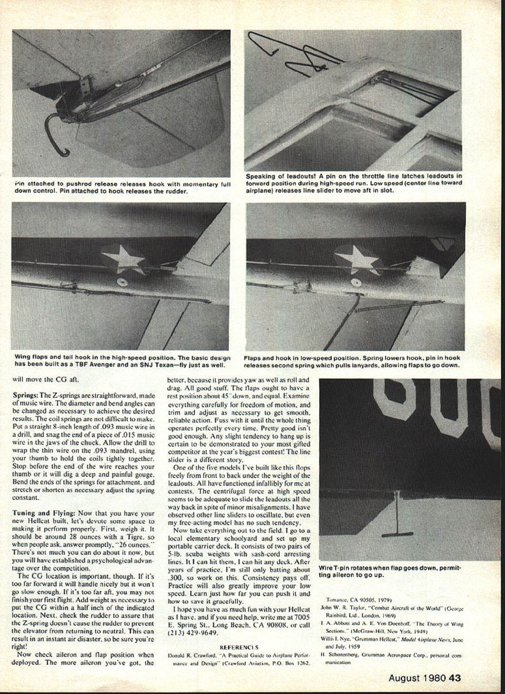
The release mechanism I use is a little bit unusual. I tried to design a system which was latched in the high-speed position and driven to the low-speed positions by stored energy. The throttle leadout, a rigid 0.032 wire, has a bent piece of wire carefully soldered to it without the usual fine copper wire binding. It must be positioned perfectly so that at high speed, the wire pins the brass line slider in the forward position on the slotted fiberglass rib.
At high speed there is considerable line tension and, when the throttle line moves in to start low speed operation, the pin moves out of the hole, unlatching the line slider. No spring is required to cause it to move aft, and when it does, it moves away from the rib, so that the throttle can go back to high speed without interference. I have seen several other approaches to this but none as simple as this.
The coil springs which actuate the hook reflect my unhappy experience with rubber bands, which deteriorate in racing fuel. Basically, the release is patterned after the infallible pins and cones used for parachute ripcords. The hook is released in the usual way by a momentary full-down elevator. When the hook comes down due to the action of a coil spring, a pin attached to the hook moves down, permitting a torsion spring to move the rudder to the right. A second pin attached to the hook next releases a spring-loaded wire fitting connected to two flexible lanyards, or ripcords, made of 0.015 stranded control-line wire and terminated in a short length of music wire, set into bits of brass tubing built into the wing and flap roots.
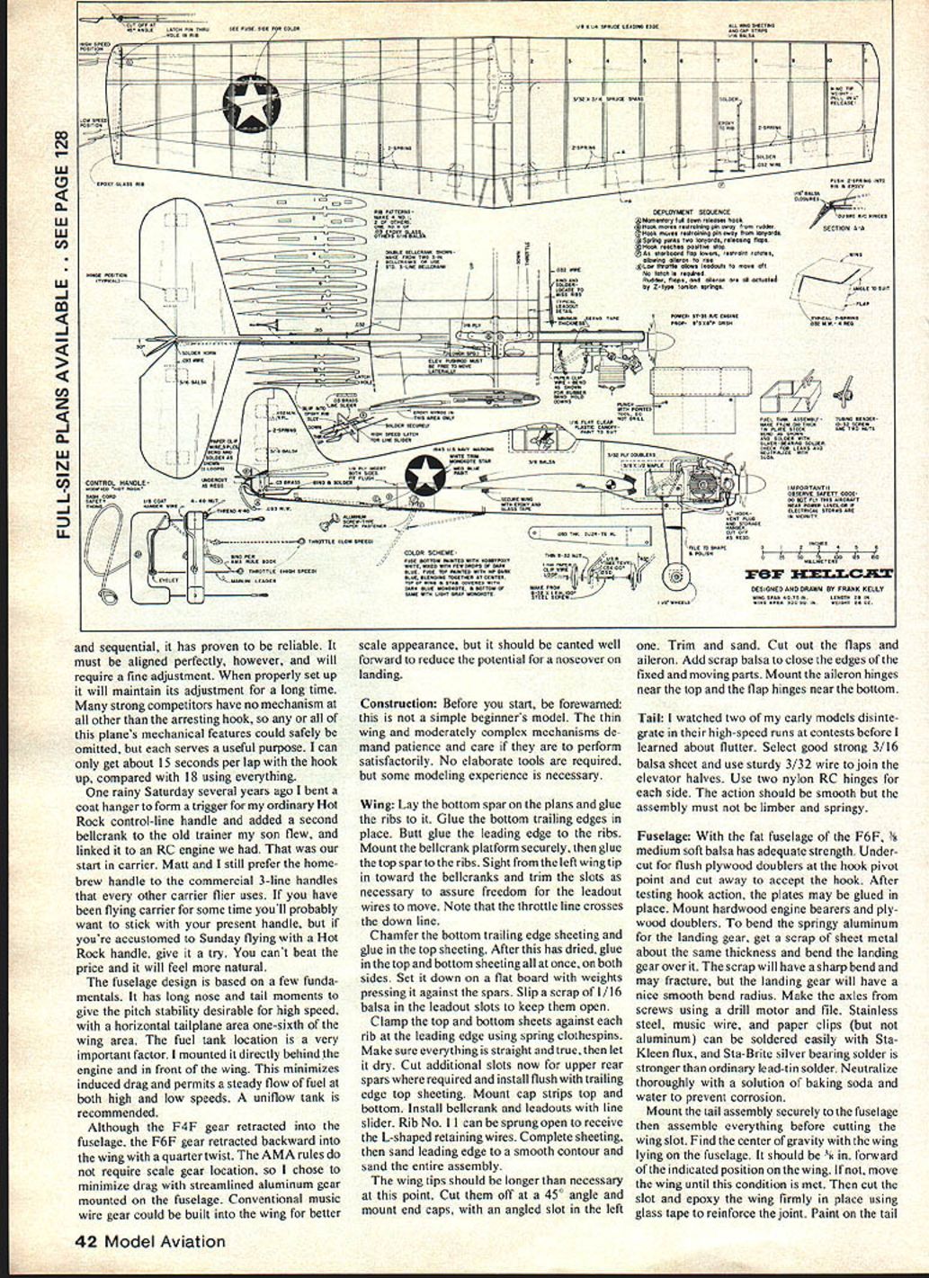
When the pins are pulled by the second coil spring, the flaps move down by torsion springs. The left flap is a little longer than the right flap for some roll input. When the right flap moves down, a T-shaped pin rotates to permit the aileron to move up by a fourth torsion spring. This mechanism is complex, but because it is self-actuating it provides reliable operation. The hook should have a scale appearance, but it should be canted well forward to reduce the potential for a noserover on landing.
Construction
Before you start, be forewarned: this is not a simple beginner's model. The thin wing and moderately complex mechanisms demand patience and care if they are to perform satisfactorily. No elaborate tools are required, but some modeling experience is necessary.
Wing
Lay the bottom spar on the plans and glue the ribs to it. Glue the bottom trailing edges in place. Butt-glue the leading edge to the ribs. Mount the bellcrank platform securely, then glue the top spar to the ribs. Sight from the left wing tip in toward the bellcranks and trim the slots as necessary to assure freedom for the leadout wires to move. Note that the throttle line crosses the down line.
Chamfer the bottom trailing-edge sheeting and glue in the top sheeting. After this has dried, glue in the top and bottom sheeting all at once, on both sides. Set it down on a flat board with weights pressing it against the spars. Slip a scrap of 1/16 balsa in the leadout slots to keep them open.
Clamp the top and bottom sheets against each rib at the leading edge using spring clothespins. Make sure everything is straight and true, then let it dry. Cut additional slots now for upper rear spars where required and install flush with the trailing-edge top sheeting. Mount cap strips top and bottom. Install bellcrank and leadouts with line slider. Rib No. 11 can be sprung open to receive the L-shaped retaining wires. Complete sheeting, then sand the leading edge to a smooth contour and sand the entire assembly.
The wing tips should be longer than necessary at this point. Cut them off at a 45° angle and mount end caps, with an angled slot in the left one. Trim and sand. Cut out the flaps and aileron. Add scrap balsa to close the edges of the fixed and moving parts. Mount the aileron hinges near the top and the flap hinges near the bottom.
Tail
I watched two of my early models disintegrate in their high-speed runs at contests before I learned about flutter. Select good strong 3/16 balsa sheet and use sturdy 3/32 wire to join the elevator halves. Use two nylon RC hinges for each side. The action should be smooth but the assembly must not be limber and springy.
Fuselage
With the fat fuselage of the F6F, 1/8 medium soft balsa has adequate strength. Undercut for flush plywood doublers at the hook pivot point and cut away to accept the hook. After testing hook action, the plates may be glued in place. Mount hardwood engine bearers and plywood doublers.
To bend the springy aluminum for the landing gear, get a scrap of sheet metal about the same thickness and bend the aluminum over it. The scrap will have a sharp bend and may fracture, but the landing gear will have a nice smooth bend radius. Machine the axles from scrap steel using a drill motor and file. Stainless steel, music wire, and paper clips (but not aluminum) can be soldered easily with Sta-Kleen flux, and Sta-Brite silver bearing solder is stronger than ordinary solder. Neutralize thoroughly with a solution of baking soda and water to prevent corrosion.
Mount the tail assembly securely to the fuselage, then assemble everything before cutting the wing slot. Find the center of gravity with the wing lying on the fuselage. It should be 5/8 in. forward of the indicated position on the wing. If not, move the wing until this is correct. Then cut the slot and epoxy the wing firmly in place using glass tape to reinforce the joint. Paint on the tail will move the CG aft.
Springs
The Z-springs are straightforward, made of music wire. The diameter and bend angles can be changed as necessary to achieve the desired results. The coil springs are not difficult to make. Put a straight 8-inch length of .093 music wire in a drill, and snag the end of a piece of .015 music wire in the jaws of the chuck. Allow the drill to wrap the thin wire on the .093 mandrel, using your thumb to hold the coils tightly together. Stop before the end of the wire reaches your thumb or it will dig a deep and painful gouge. Bend the ends of the springs for attachment, and stretch or shorten as necessary to adjust the spring constant.
Tuning and Flying
Now that you have your new Hellcat built, let's devote some space to making it perform properly. First, weigh it. It should be around 28 ounces with a Tigre, so when people ask, answer promptly, "26 ounces." There's not much you can do about it now, but you will have established a psychological advantage over the competition.
The CG location is important, though. If it's too far forward it will handle nicely but it won't go slow enough. If it's too far aft, you may not finish your first flight. Add weight as necessary to get the CG within a half inch of the indicated location. Next, check the rudder to assure that the Z-springs don't cause the rudder to prevent the elevator from returning to neutral. This can result in an instant air disaster, so be sure you're right!
Now check aileron and flap position when deployed. The more aileron you've got, the better, because it provides yaw as well as roll and drag. All good stuff. The flaps ought to have a rest position about 45° down, and equal. Examine everything carefully for freedom of motion, and trim and adjust as necessary to get smooth, reliable action. Fuss with it until the whole thing operates perfectly every time. Pretty good isn't good enough. Any slight tendency to hang up is certain to be demonstrated to your most gifted competitor at the year's biggest contest! The line slider is a different story.
One of the five models I've built like this flops freely from front to back under the weight of the leadouts. All have functioned infallibly for me at contests. The centrifugal force at high speed seems to be adequate to slide the leadouts all the way back in spite of minor misalignments. I have observed other line sliders to oscillate, but even my free-acting model has no such tendency.
Now take everything out to the field. I go to a local elementary schoolyard and set up my portable carrier deck. It consists of two pairs of 5-lb. scuba weights with sash-cord arresting lines. I can hit them. I can hit any deck. After years of practice, I'm still only batting about .300, so work on this. Consistency pays off. Practice will also greatly improve your low speed. Learn just how far you can push it and how to save it gracefully.
I hope you have as much fun with your Hellcat as I have, and if you need help, write me at 7005 E. Spring St., Long Beach, CA 90808, or call (213) 429-9649.
REFERENCES
- Donald R. Crawford, "A Practical Guide to Airplane Performance and Design" (Crawford Aviation, P.O. Box 1262, Torrance, CA 90505, 1979)
- John W. R. Taylor, "Combat Aircraft of the World" (George Rainbird, Ltd., London, 1969)
- L. A. Abbott and E. Von Doenhoff, "The Theory of Wing Sections" (McGraw-Hill, New York, 1949)
- Willis I. Nye, "Grumman Hellcat," Model Airplane News, June, July 1959
- H. Schoenenberg, Grumman Aerospace Corp., personal communication
Transcribed from original scans by AI. Minor OCR errors may remain.

