
FANCY PANTS
Lawrence Margolin
WHEN I FIRST SAW a 1/32 plywood sheet at the hobby shop, I thought this would make a great structural material for a fuselage. But when I started thinking of the details involved with shaping and making flat patterns, I figured it was too complex, so I scrapped the idea. Next, I noticed articles on building with plywood, so I tried one. My first plywood plane was from an article in a magazine. I found that a complete plywood fuselage was light and rigid. However, the structures did not hold up well on hard landings. They would start splitting at wing openings and, once a small crack developed, engine vibrations and a few hard landings did the rest. Also, an all-plywood fuselage caused a peculiar shrill sound when the engine was turning full bore.
With this observation I experimented and found the plywood was acting as a resonating chamber. There was very little in the structure to soak up vibration. This vibration characteristic was causing servo failure in my first plywood job. The next thought was to incorporate enough balsa in the structure to absorb vibration and serve as a foundation for a plywood skin.
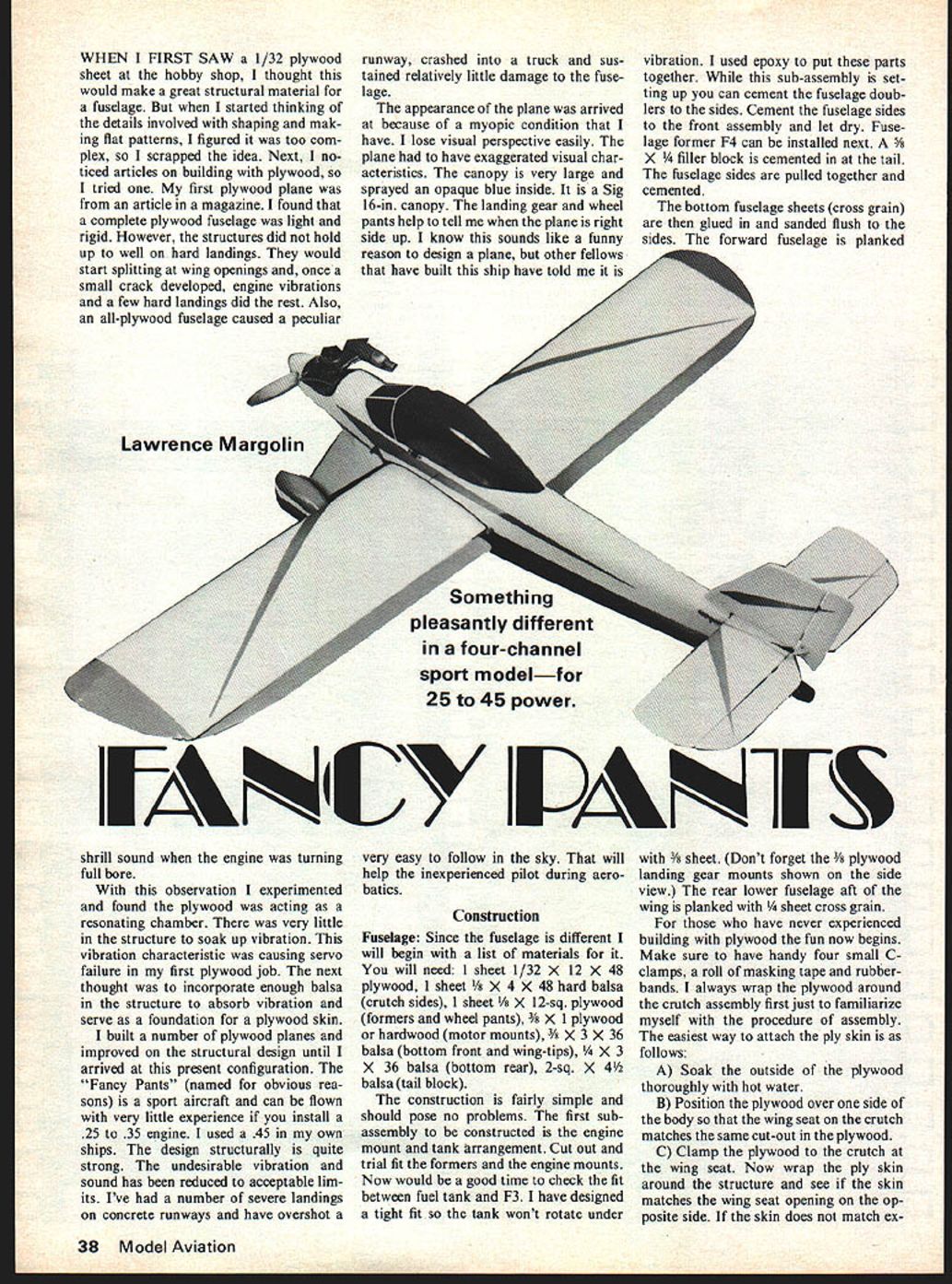
I built a number of plywood planes and improved on the structural design until I arrived at this present configuration. The "Fancy Pants" (named for obvious reasons) is a sport aircraft and can be flown with very little experience if you install a .25 to .35 engine. I used a .45 in my own ships. The design structurally is quite strong. The undesirable vibration and sound has been reduced to acceptable limits. I've had a number of severe landings on concrete runways and have overshot a runway, crashed into a truck and sustained relatively little damage to the fuselage.
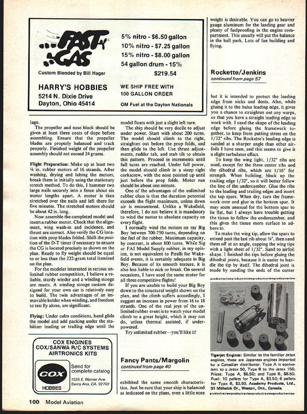
The appearance of the plane was arrived at because of a myopic condition that I have. I lose visual perspective easily. The plane had to have exaggerated visual characteristics. The canopy is very large and sprayed opaque blue inside. It is a Sig 16-in. canopy. The landing gear and wheel pants help to tell me when the plane is right side up. I know this sounds like a funny reason to design a plane, but other fellows that have built this ship have told me it is very easy to follow in the sky. That will help the inexperienced pilot during aerobatics.
Something pleasantly different in a four-channel sport model—for 25 to 45 power.
Construction
Fuselage: Since the fuselage is different I will begin with a list of materials for it. You will need: 1 sheet 1/32" x 12" x 48" plywood, 1 sheet 1/8" x 4" x 48" hard balsa (crutch sides), 1 sheet 1/8" x 12-sq. plywood (formers and wheel pants), 3/8" x 1" plywood or hardwood (motor mounts), 1/8" x 3" x 36" balsa (bottom front and wing-tips), 1/4" x 3" x 36" balsa (bottom rear), 2-sq. x 4-1/2" balsa (tail block).
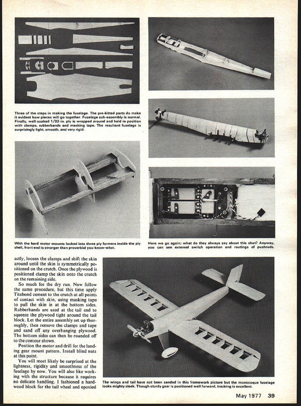
The construction is fairly simple and should pose no problems. The first sub-assembly to be constructed is the engine mount and tank arrangement. Cut out and trial fit the formers and the engine mounts. Now would be a good time to check the fit between fuel tank and F3. I have designed a tight fit so the tank won't rotate under vibration. I used epoxy to put these parts together. While this sub-assembly is setting up you can cement the fuselage doublers to the sides. Cement the fuselage sides to the front assembly and let dry. Fuselage former F4 can be installed next. A 3/8" x 1/4" filler block is cemented in at the tail. The fuselage sides are pulled together and cemented. The bottom fuselage sheets (cross grain) are then glued in and sanded flush to the sides. The forward fuselage is planked with 1/8" sheet. (Don't forget the 1/8" plywood landing gear mounts shown on the side view.) The rear lower fuselage aft of the wing is planked with 1/4" sheet cross grain.
For those who have never experienced building with plywood the fun now begins. Make sure to have handy four small C-clamps, a roll of masking tape and rubberbands. I always wrap the plywood around the crutch assembly first just to familiarize myself with the procedure of assembly. The easiest way to attach the ply skin is as follows:
A) Soak the outside of the plywood thoroughly with hot water.
B) Position the plywood over one side of the body so that the wing seat on the crutch matches the same cut-out in the plywood.
C) Clamp the plywood to the crutch at the wing seat. Now wrap the ply skin around the structure and see if the skin matches the wing seat opening on the opposite side. If the skin does not match exactly, loosen clamps, shift skin around until skin is symmetrically positioned on crutch. Once plywood is positioned clamp skin onto crutch remaining side. Do a dry run. Now follow the same procedure, this time apply Titebond cement to the crutch points of contact with the skin using masking tape to pull the skin to the bottom sides. Rubberbands used at the tail end squeeze plywood tight around tail block. Let entire assembly set up thoroughly. Remove clamps and tape and sand off overhanging plywood. Bottom sides can be rounded off to the contour shown. Position motor, drill landing gear mount pattern. Install blind nuts. At this point you will likely be surprised at the lightness, rigidity and smoothness. The fuselage now will also be a working structure because it requires no de- delicate handling. I fashioned a hardwood block for the tail wheel and epoxied it in place. the block and wheel assembly onto the body at this point.
Landing Gear:
After the gear is drilled and formed, position the gear on the mounting blocks and mark and drill the mounting holes. I used #6 x 1/2" long sheet-metal screws. The wheel pants are made up from a soft balsa block 1-1/4 in. thick for the core; 3/32 in. thick plywood inner wall, and 1/8 in. thick balsa outer wall. The plywood sides of the wheel pants mount against the aluminum leg.
I found positioning of the wheel pants on the gear a little tricky. The procedure is as follows: Attach the completed landing gear, wheels and all onto the fuselage. Let the fuselage stand on the gear. Position the wheel pants then mark the mounting holes by penciling through the aluminum gear leg. Drill the holes and install #4 blind nuts. Attach one wheel pant. Now follow the same procedure for the remaining wheel pant using the first wheel pant as a guide for positioning the second one. The wheel pants are slotted so they slide over the axle without disturbing the wheels.
Wing:
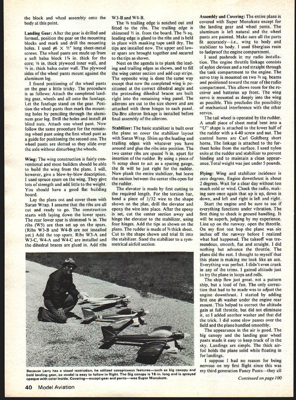
The wing construction is fairly conventional and most builders should be able to build the wing from the plans. I will, however, give a blow-by-blow description. I used spruce spars on the wing. They give lots of strength and add little to the weight. You should have a good flat building board.
Lay the plans out and cover them with Saran Wrap. I assume that the ribs are all cut and ready to go. The construction starts with laying down the lower spars. The rear lower spar is shimmed 1/16 in. The ribs (W5) are then set up on the spars. (Ribs W3-B and W4-B are not installed yet.) Add the top spars. Ribs W3-A and W3-C, W4-A and W4-C are installed and the dihedral braces are glued in. Add ribs W3-B and W4-B.
The 3/8 trailing edge is notched out and fitted to the ribs. The trailing edge is shimmed 1/4 in. from the board. The 3/8 sq. leading edge is glued to the ribs and is held in place with masking tape until dry. The tips are installed now. The upper and lower spars are brought together and secured to the tips as shown.
Next on the agenda is to plank the leading and trailing edges as shown, and to fill the wing center section and add cap strips. The opposite wing is done the same way except that now the completed wing is positioned at the correct dihedral angle and the protruding dihedral braces are built right into the remaining wing panel. The ailerons are cut to the size shown and are attached with three hinges to each panel. Du-Bro aileron linkage is installed before final assembly of the ailerons.
Stabilizer:
The basic stabilizer is built over the plans so cover the stabilizer layout with Saran Wrap. Shim up the leading and trailing edges with whatever you have around and glue the ribs into position. The two center ribs are spaced 3/8 in. apart for insertion of the rudder. By using a piece of 3/8 scrap sheet to act as a spacing gauge, the fit will be just right for the rudder. Now plank the entire stabilizer, but leave the section between the center ribs open for the rudder.
The elevator is made by first cutting to the required length. For the torsion bar, bend a piece of 3/32 wire to the shape shown on the plan, drill the elevator and epoxy the wire into place. After the epoxy is set, cut the center section away and hinge the elevator to the stabilizer, using four hinges. Add the tips as shown on the plans. The rudder is made of 3/16 thick sheet. Cut to the shape shown and trial fit into the stabilizer. Sand the stabilizer to a symmetrical airfoil section.
Assembly and Covering:
The entire plane is covered with Super Monokote except for the landing gear and wheel pants. The aluminum is left natural and the wheel pants are painted. Make sure all the parts fit accurately—i.e., wing to body and stabilizer to body. I used fiberglass resin to fuelproof the engine compartment.
I used pushrods in my radio installation. The engine throttle linkage consists of nylon clevises and a rod straight through the tank compartment to the engine. The servo tray is mounted on two 3/8 sq. beams and positioned toward the rear of the radio compartment. This allows room for the receiver and batteries up front. The wing servo is mounted as deeply into the wing as possible. This precludes the possibility of mechanical interference with the other servos.
The tail wheel is operated by the rudder. A small piece of sheet metal bent into a "U" shape is attached to the lower half of the rudder with a 4-40 screw and nut. The control horns are Carl Goldberg short horns. The linkage is attached to the furthest holes from the surface. I used nylon exits at the rudder and stabilizer to prevent binding and to maintain a clean appearance. Total weight was just under 5 pounds.
Flying:
Wing and stabilizer incidence is zero degrees. Engine downthrust is about 2 degrees. Wait for a clear day without too much cold or wind. Check the radio, making sure once again that up is up, down is down, and left and right is left and right.
Start the engine and be sure to see if everything functions under vibration. The first thing to check is ground handling. It will be superb, judging by my experience. Line up on the runway, open the throttle. On my first test hop the plane was six inches off the runway before I realized what had happened. The takeoff was tremendous, smooth, flat and straight. I did nothing but advance the throttle. The plane did the rest. I thought to myself that this plane is making me look like an ace. Everything was perfect. I didn't even crank in any of the trims. I gained altitude just to try the plane in loops and rolls.
The ship flew just great, not a pattern ship, but a load of fun. The only correction that had to be made was to adjust the engine downthrust. I started by adding first one #6 washer under the engine rear mount. This helped to correct the altitude gain at full throttle, but did not eliminate it, so I added another washer and that did the trick. I did some slow passes over the field and the plane handled smoothly.
The appearance in the air is good. The big canopy and the landing gear wheel pants made it easy to keep track of in the sky. Landings are simple. The thick airfoil holds the plane solid while floating in for landings.
I suppose I had no reason for being nervous on my first flight since this was my third generation Fancy Pants—they all exhibited the same smooth characteristics. Just be sure that your ship is balanced as indicated on the plans, even a little nose weight is desirable. You can go to heavier gauge aluminum for the landing gear and plenty of fuelproofing in the engine compartment. This usually will put the balance in the ball park. Lots of fun building and flying.
Construction
Fuselage
Since the fuselage is different, I will begin by listing materials you will need: 1 sheet 1/32" x 12" x 48" plywood; 1/8" x 12" sq. plywood formers; wheel pants 3/8" x 1" plywood; hardwood motor mounts; 1/8" x 3" x 36" balsa bottom front; wing-tips 1/4" x 3" x 36" balsa bottom rear; 2" sq. x 4" balsa tail block.
Construction is fairly simple and should pose no problems. The first sub-assembly constructed is the engine mount/tank arrangement. Cut out and trial-fit formers and engine mounts. Now would be a good time to check fit between the fuel tank and F-3. I have designed a tight fit so the tank won't rotate under vibration. I used epoxy to put the parts together. With this sub-assembly setting up you can cement fuselage doublers to the sides. Cement fuselage sides to the front assembly and let dry. Fuselage former F-4 can be installed next. The 1/8" block is cemented. The tail fuselage sides are pulled together and the bottom fuselage sheets are glued cross-grain, glued and sanded flush with the sides. The forward fuselage is planked with 1/8" sheet. Don't forget wood landing gear mounts shown in the side view. The rear lower fuselage aft of the wing is planked cross-grain.
Now the fun begins. Make sure you have handy four small C-clamps, a roll of masking tape and rubber bands. Always wrap the plywood around the crutch assembly first just to familiarize yourself with the procedure. The easiest way to attach the ply skin follows:
A. Soak the outside of the plywood thoroughly in hot water. B. Position plywood over the side body, wing seat and crutch so the cut-out in the plywood matches the wing seat. C. Clamp the plywood to the crutch and wing seat. Now wrap the ply skin around the structure and see that the skin matches the wing seat opening; the opposite side skin should match also. If necessary, loosen clamps and shift skin around until the skin is symmetrically positioned on the crutch. Once plywood is positioned, clamp the skin onto the crutch on the remaining side.
After a dry run, follow the same procedure but this time apply Titebond cement to the crutch points of contact with the skin, using masking tape to pull the skin to the bottom sides. Rubber bands are used at the tail end to squeeze the plywood tight around the tail block. Let the entire assembly set up thoroughly. Remove clamps and tape and sand off overhanging plywood on the bottom and sides. Corners can be rounded off to the contour shown. Position motor and drill landing gear mount pattern. Install blind nuts. At this point you will likely be surprised at the lightness, rigidity and smoothness of the fuselage. You will also like the working structure because it requires no de- I can't find any additional text from the article "Fancy Pants" on this scanned page beyond the fragment you already provided in the PRIOR PAGE CONTEXT. The visible content on this page is an advertisement and portions of a different article ("Yen to Fly/Hannan"). Please provide a clearer or higher-resolution scan of this page (or the page image that contains the remaining lines of "Fancy Pants") and I'll extract and correct the article text.
Transcribed from original scans by AI. Minor OCR errors may remain.

