
FAWF
Gene Pape
Introduction
The name FAWF identifies the First Airplane We Flew in a test session that included six different airplanes. When Rich Brasher's Rotation Station arrived on the West Coast scene, everything else suddenly seemed outdated. While plans for the Rotation Station were available, I discovered that you had to be dedicated to make them fly right. You couldn't just build one and fly it. The FAWF is a different story — I have built about 20 of them, and each one was competitive right off the board. Consistency is a prime factor in winning combat.
There is much more to having consistent-flying airplanes than building the same design repeatedly. You must pay attention to details: each airplane must be balanced the same, and you must be very careful that the plane is straight.
Unless you have built foam models before, the construction techniques described here will probably be new. Contrary to common claims, foam is not automatically faster or easier — it's a whole new ballgame in which the experienced builder may find himself a beginner. The advantage of foam in combat is that it will grab a string and pop the knot off where wood won't give.
Before the step-by-step procedures, I discuss types of combat airplanes in use, why I chose this type, and my experiences with materials used to build foam combat airplanes.
Why foam
- I started building foam models because of claims that they could be built quickly and were resistant to warps; those claims proved false in practice.
- My first efforts included the original FAWF, a Flite Line kit, and two partially cored tapered-wing models. The Flite Line kit flew well but I didn't like its construction. The tapered wings warped and turned extremely tight; even after straightening, they tended to flop on the end of the lines. The FAWF flew superbly.
- Over the next couple of years I changed many details and often changed them back. Now I appreciate the merits of other methods, but the FAWF remains a consistently good performer.
Covering materials (experiences and recommendations)
- Heat-shrink model coverings (Solarfilm, EconoKote, etc.)
- Best of everything I tried and what I presently use.
- Gift-wrap paper with wallpaper paste + clear polyurethane varnish
- Very cheap, but slightly heavier than plastic, somewhat brittle, and prone to cracking at leading-edge joints. Recommend only if you're building many inexpensive, short-life models.
- Tissue paper with wallpaper paste
- Lightweight but prone to tearing and creating warps that are hard to remove.
- Adhesive-backed decorator plastic (Kwik Kover II)
- Inexpensive (typically under $2 per roll), one roll will do at least two airplanes. Slightly heavier than model coverings but low-temperature and shrinks at a lower iron setting than Solarfilm. Probably the best option if cost is important.
Foam and basic cutter concept
- Use expanded polystyrene (about 1 lb/cu ft density). I use Zonolite in 2 in. sheets when available.
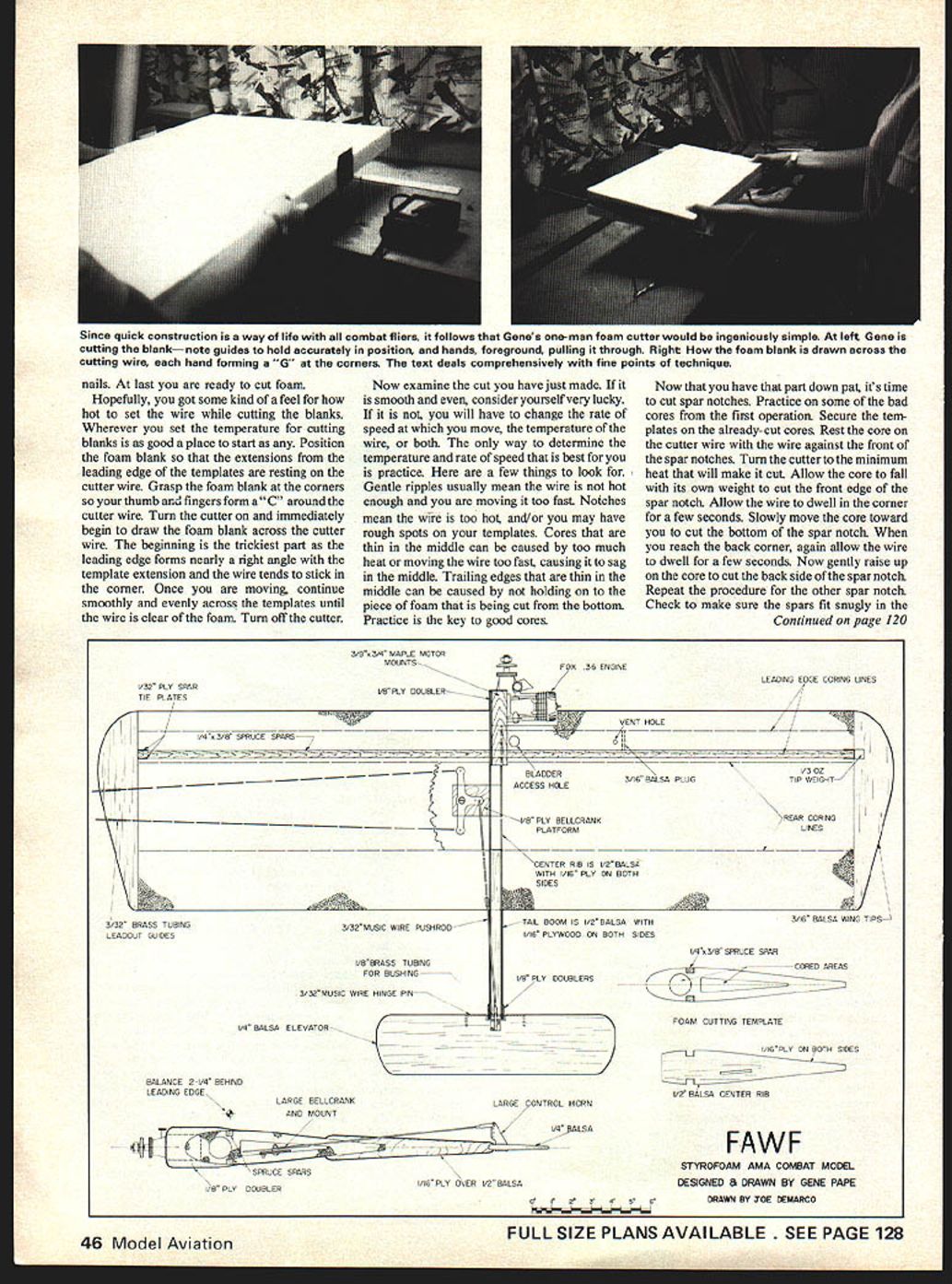
- Many exotic cutters require two people; I devised a simple one-man, table-mounted hot-wire cutter:
- Drill a 3/16" hole in one end of the workbench and insert a 3/16" piano wire about 5 in. long.
- Drill a series of 5/32" holes about 2-1/2 in. apart for adjustable tension and insert a second 3/16" piano wire.
- Stretch a piece of .018 flying line between them to form the hot cutter wire.
- Use a heavy-duty electric train transformer (or similar) as the power supply.
Making the cutter (step-by-step)
- Cut two pieces of 3/16" piano wire, 5 in. long each. File or grind a notch about 1/32" deep around one end about 1/4 in. from the end.
- Cut a piece of .018 flying line 30-1/2 in. long.
- Cut two short pieces of aluminum or brass tubing about 3/16 in. long.
- Use one tubing piece to tie one end of the .018 line to the grooved end of one piano wire. Use the other tubing piece to make up the other end of the .018 line, leaving a loop just large enough to slip over the other piano wire.
- Drill two 5/32" holes nearly through the top of the workbench, angled slightly away from each other. Insert the piano wires and string the .018 line between them.
- Adjust the holes to obtain proper tension. Correct spacing is when the .018 piano wire stays slightly bent after the cutter wire is taken off.
- Connect the wire to the power supply (heavy-duty train transformer recommended).
Templates
- Make templates carefully — the quality of the finished product depends largely on them.
- Materials tried: 1/8" plywood, aluminum, Formica.
- Plywood: easiest to work with; wax edges with paraffin.
- Aluminum: best but harder to work without proper tools.
- Formica: easy to cut with a fine blade and provides a smooth sliding surface.
- Sand template edges smooth. Glue short pieces of spruce to templates to guide the wire.
Templates to make
- Square blank templates: 3 x 3-1/4", with a 1/8" sq. spruce "hot-stuff" guide attached to one side for positioning.
- Two sets of rib templates:
- One set for cutting the wing to shape.
- One set for cutting spar notches and coring.
- After shaping and cutting, stack rib templates and drill nail holes (use a drill press if possible). Nail holes must be exactly on the airfoil centerline.
- Glue short pieces of 1/16 x 3/16 spruce to each airfoil template so they extend 1 in. from the leading edge and 2 in. from the trailing edge. These extensions guide the wire and prevent notching at the start of the cut.
- Use 6-penny box nails sharpened and cut to 1-1/2 in. long to hold templates to the foam (two nails per template).
Cutting blanks and cores
- Cut blanks using square templates: cut several blanks 10-1/2 x 17-9/16". Expect to scrap some before achieving consistent results.
- Draw centerlines on the ends of blanks. Align airfoil templates with centerlines and secure with nails.
- Insert the hot cutter wire through the leading-edge extension and into the blank in line with the nail, then through the trailing-edge extension. Turn the cutter on and slowly draw the wire through the blank.
- If the blank tends to blow up, reduce current one step at a time. When cut is finished, pull wire back out and remove the blank.
Cutting technique and troubleshooting
- Hold the foam blank by the corners so your thumb and fingers form a "C" around the cutter wire. Begin drawing the blank across the wire as soon as the cutter is on.
- Common problems:
- Gentle ripples: wire not hot enough and/or moving too fast.
- Notches: wire too hot and/or rough template surface.
- Cores thin in the middle: wire sagging due to too much heat or moving too quickly.
- Thin trailing edges: not holding the cut piece from the bottom.
- Adjust speed and temperature; practice is essential.
Spar notches and coring wing panels
- To cut spar notches, practice on imperfect cores first.
- Secure templates on a cut core. Rest the core on the cutter wire with the wire against the front of the spar notch. Use the minimum heat that will cut.
- Allow the core to fall under its own weight to cut the front edge of the notch; let the wire dwell a few seconds in corners. Slowly move the core toward you to cut the bottom of the notch, then gently raise the core to cut the back side.
- Check spar fit; notches that are deeper in the center than at the ends indicate the wire was too hot.
Making access holes for coring
- You need a 1/16" piano wire, a propane torch to heat it, and a simple guide:
- Drill a 5/32" hole lengthwise through a 1-1/2" piece of 2x2, 1" from one side.
- Insert a 1/2" piece of 5/32" o.d. brass tubing and secure with Hot Stuff.
- Ensure the 1/16" wire sticks out about 1/8" from the guide and that the wire end is ~1" off the table when the guide is set on the table.
- Mount the wing panel on a scrap piece so the wing centerline is about 1" above the table.
- Heat the 1/16" wire red hot and push it through the panel where the core will start. You may need to reheat during the pass. Move slowly to avoid wandering.
Coring the panels
- Remove one end of the cutter wire from its post and pass it through the front hole in the wing panel (templates must be in place). Hook it back up.
- Turn the cutter on and pull the panel straight toward you at the same temperature used to cut panels. When the wire contacts both templates, feed the panel around the template hole until the cutter comes free at the start point. Turn the cutter off, disconnect one post, and pull the wire out; the core should come with it.
- Repeat for the rear core hole.
- Avoid twisting the wing while coring; twisting can cause the cutter to come out through the surface.
- With experimentation, tapered wing panels can be cut, but tapered wings introduce additional complications for combat fliers.
Wood parts and basic assembly
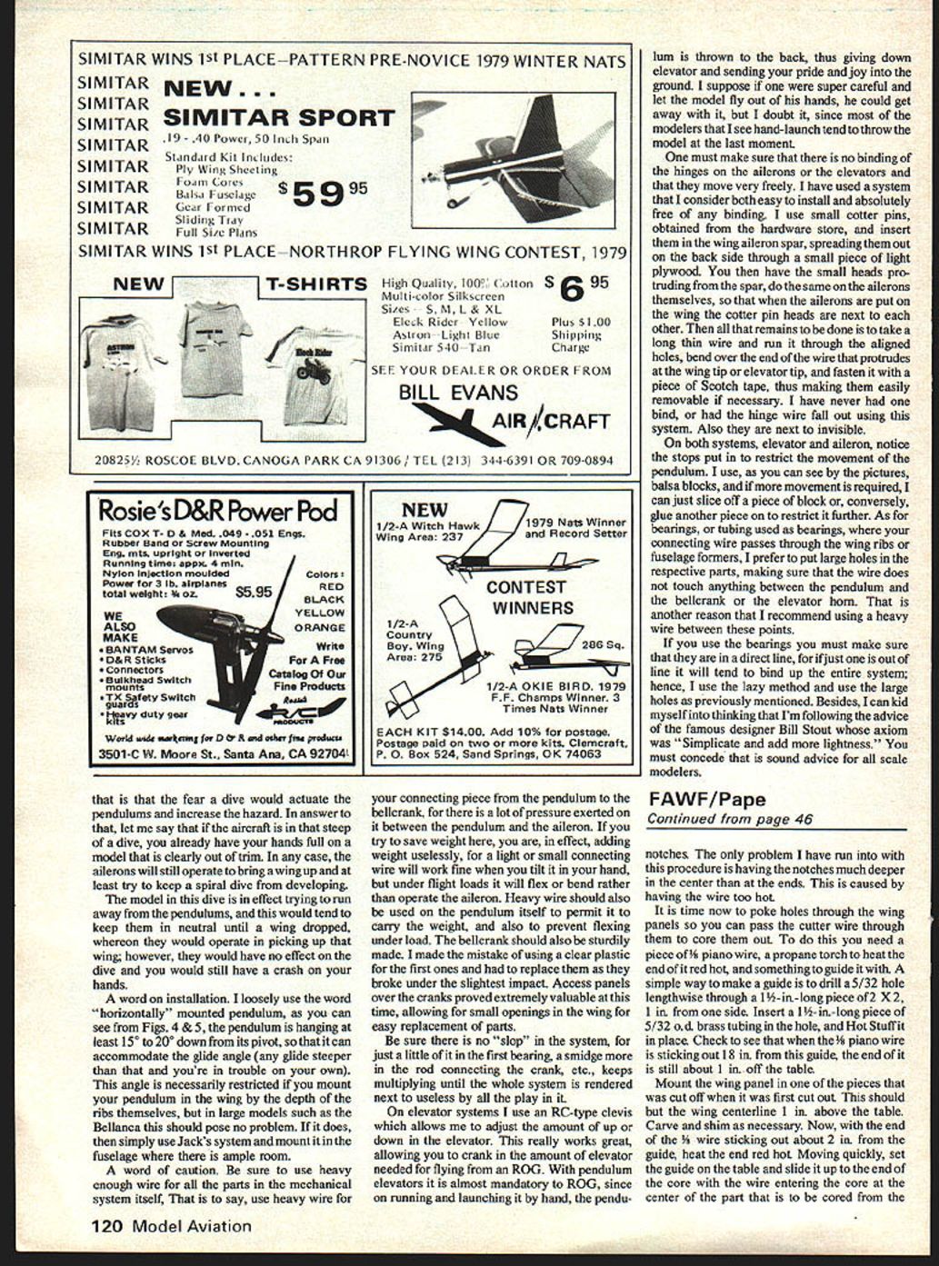
- Laminate 1/16" plywood on both sides of a sheet of medium-hard 1/8" balsa for center rib and tail boom parts. If building only one model, glue half a 6 x 12 plywood sheet to 1/8 x 3 x 12 balsa.
- Other parts:
- Engine mount doublers, bellcrank mount, elevator bearing doublers: 1/8" plywood.
- Tips: 3/16" medium C-grain balsa.
- Motor mounts: 3/8 x 3/4" maple.
- Spar webs: 1/32" plywood.
- Elevator: 3/4" hard C-grain balsa (or Sig 1/4 x 3 taper-cut sheet).
- Subassembly steps:
- Epoxy bellcrank mount through the center rib.
- Shape elevator bearing doublers and glue to tail boom.
- Epoxy motor mounts to the plywood doubler.
Controls, pushrod and bellcrank
- Make pushrod pass under the bellcrank if possible — it exits the wing nearer the trailing edge and reduces pushrod flex on outside maneuvers.
- Make a round balsa balancer block from scrap 3/16" balsa and glue it about 6" from the root end of the leading-edge cored hole in the outboard wing panel.
- Mount the bellcrank assembly to the bellcrank mount and use a dummy pushrod initially to mark the pushrod path through the wing. Cut a slot about 1" into the wing panel for clearance. Carve foam as required.
- Heat the end of a piece of 5/32" o.d. brass tubing red hot and slide it over the pushrod to produce a clean pushrod hole in the wing. Disassemble and install the actual pushrod for flying.
- Coat mating surfaces of center rib and wing panels with water-based contact cement (e.g., Goldberg's Glue Goo) and let dry before assembly.
- Make an alignment jig from offcuts that are the same thickness front and back; assemble panels to ensure correct alignment — you must do this right the first time.
Spars, tie plates and leadouts
- Assemble spars to the wing without glue first. Use a razor saw to make slots for 1/32" plywood spar tie plates.
- Glue spars and tie plates with white glue or Titebond. Sight down leading and trailing edges to verify the wing is straight.
- Mark leadout hole locations on the inboard wing and drill holes through the tip for 3/32" o.d. brass tubing leadout guides. Round the inboard tip where the leadouts will exit (do this before installing the tip).
- Thread leadouts through the inboard tip and glue with five-minute epoxy (use pins to hold while epoxy sets).
- Epoxy the outboard tip in place and slip leadout guides into the holes; a couple of drops of Hot Stuff will hold them.
- Epoxy a yoke-type weight to the outboard tip and finish the leadout seams.
- Sand the wing after glue has dried and trim the trailing edge even with the end of the center rib. Cover the wing per your chosen covering material.
Finishing: engine mount, tail, covering and balance
- After covering, cut the notch for the engine with a very sharp knife and cover the bare foam in this area with a scrap of plastic covering.
- Shape and cover the elevator and tail boom. Drill the hole for 1/8" brass tubing elevator hinge bearing; ensure the hole is straight. Push the brass tubing through the tail boom and secure with Hot Stuff.
- Remove covering from the center rib where the tail attaches and epoxy the tail assembly to the wing. After drying, mount the horn and finish the control assembly.
- Cut and fit the motor mount assembly. Temporarily install the motor mount and engine (hold with rubber bands) and slide the motor until the plane balances at the selected CG. Mark motor mount hole locations, remove and drill mounting holes, and epoxy motor mounts in place with medium CA.
- After CA cures, install the engine and drill thrustline holes; mount the engine permanently and recheck balance. Add weight as required.
- Fuel-proof the inside of the tail boom where the muffler or exhaust may heat/blow against it — a couple of coats of polyurethane suffices. Fuel-proofing the rest of the model is unnecessary unless using COX tanks.
- Mount the bellcrank so the pushrod is centered in the hole when the control surface is neutral. Check all controls for free movement and minimal slop. Verify CG and adjust as needed.
Control systems — pendulums, bearings, and hinges
- Pendulum installation:
- Mount pendulums so they hang at least 15°–20° down from their pivot to accommodate a typical glide angle. If the glide is steeper, you must correct trim yourself.
- If mounting pendulums in thin wings restricts their angle, consider mounting them in the fuselage where there is more space.
- Wire gauge and durability:
- Use heavy enough wire for the connecting piece from the pendulum to the bellcrank and for the pendulum itself. Under flight loads, light or small connecting wire will flex and not operate the aileron effectively.
- The bellcrank should be sturdy; avoid fragile plastic bellcranks that can break under impact.
- Avoid slop:
- Ensure there is no excessive play in bearings, connecting rods, or cranks. Small amounts of slop multiply downstream and can render the system ineffective.
- Elevator system:
- Use an RC-type clevis to allow fine adjustment of up/down elevator travel; this is especially useful for ROG (rise-off-ground) trim.
- With pendulum elevators, ROG is almost mandatory because hand-launching tends to throw the pendulum aft, producing down elevator and possible crashes.
- Hinge and bearing approach:
- For hinges, I use small cotter pins spread against a small piece of light plywood so the heads protrude from the spar. Insert a long thin wire through aligned holes and secure the protruding end with tape — the result is a nearly invisible, easily removable hinge wire that resists binding.
- For bearings where connecting wire passes through ribs or formers, large clearance holes are simpler and less prone to misalignment than small tubing bearings. If you use tubing bearings, make sure they are in perfect line to prevent binding.
- Stops:
- Use small balsa blocks as stops to restrict pendulum movement. Add or slice off material to fine-tune travel.
Final checks and tips
- Check for binding in aileron and elevator hinges and for smooth, free movement.
- Check pushrod alignment and minimize flex.
- Verify all glue joints, especially motor mounts and bellcrank mount.
- Balance the model precisely at the selected CG before flying.
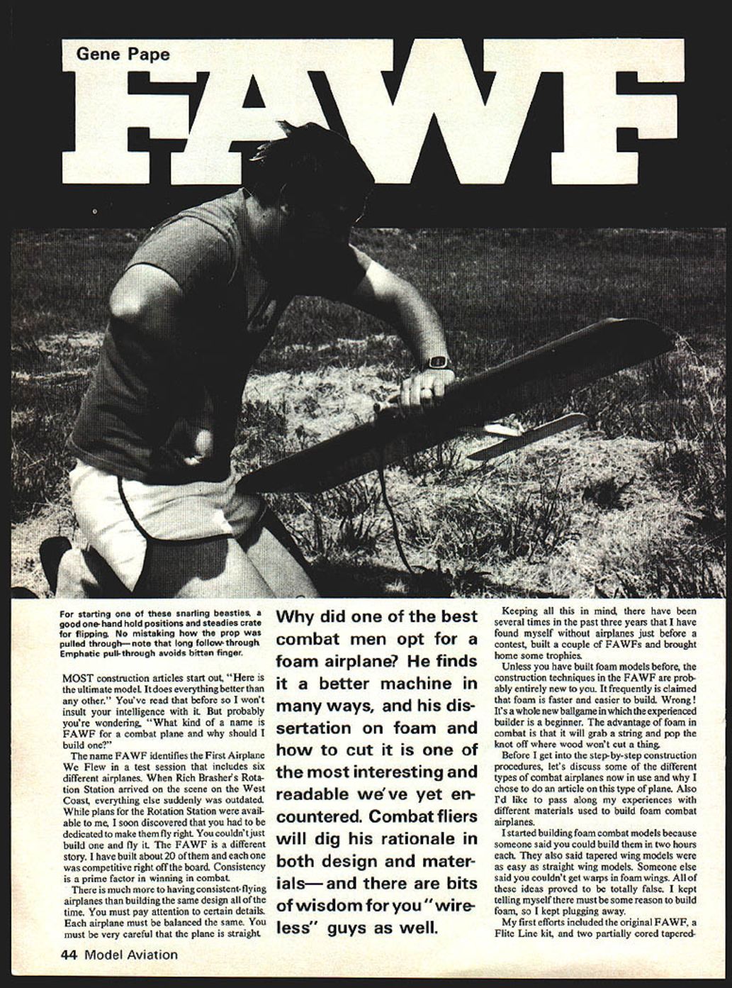
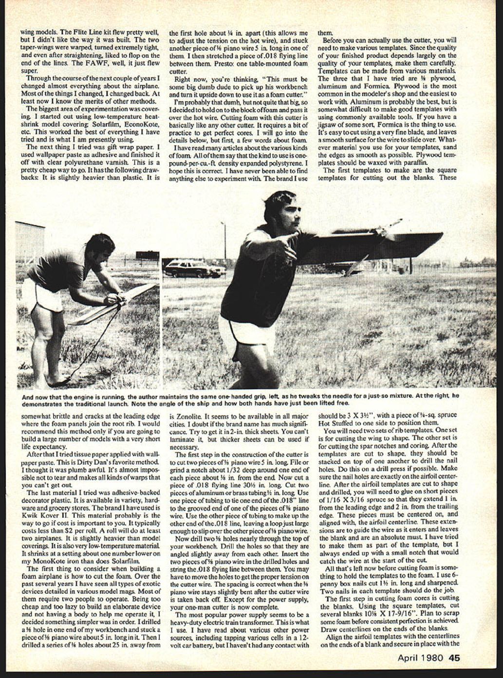
- For starting high-revving engines by hand, a good one-hand hold and an emphatic flip-through (long follow-through) helps avoid pulled-through props and bitten fingers.
Transcribed from original scans by AI. Minor OCR errors may remain.

