
FF Duration
Louis Joyner, 6 Saturday Rd., Mt. Pleasant SC 29464
ON THE DIAGONAL:
In the days before carbon fiber and other high-tech materials, building a stiff, warp-resistant wing was a challenge. You could use a sheet-balsa D-box or a completely sheeted wing, but the weight penalty was often more than you, or more accurately the model, could bear. For lightweight structures, the tissue covering offered some increase in torsional stiffness, until it went limp in the rain or on a humid morning. Multispar construction also helped by breaking the wing structure into many small panels. But for a balance between light weight and increased stiffness, the use of diagonal ribs provided the best option.
These structures took on many forms. The simplest added square strips of balsa running diagonally between the spar and trailing edge, but the 1/16-inch or 3/32-inch square balsa strips could flex under load. A better approach was to use full-depth diagonal ribs. The extra depth of the rib would limit bending in the vertical plane, while the covering would help keep the rib from bending from side to side. For optimum stiffness in torsion, these diagonal ribs need to be set at approximately 45°. During the 1950s and 1960s, a number of variations developed. The British popularized the Union Jack construction, with diagonal ribs crossing at midchord. Straight ribs offered extra support for the leading edge, spar, and trailing edge, and helped preserve the airfoil. The Italians developed a fully geodetic structure with only diagonal ribs, each crossing three or four others.
More recently, several modelers have combined diagonal ribs with carbon-capped ribs. These typically use the diagonals only in front of the spar—not behind it. Like the typical carbon-fiber D-box construction, the idea is to make the front third of the wing strong and stiff, then use the carbon-capped aft ribs as beams to tie the trailing edge to the spar.
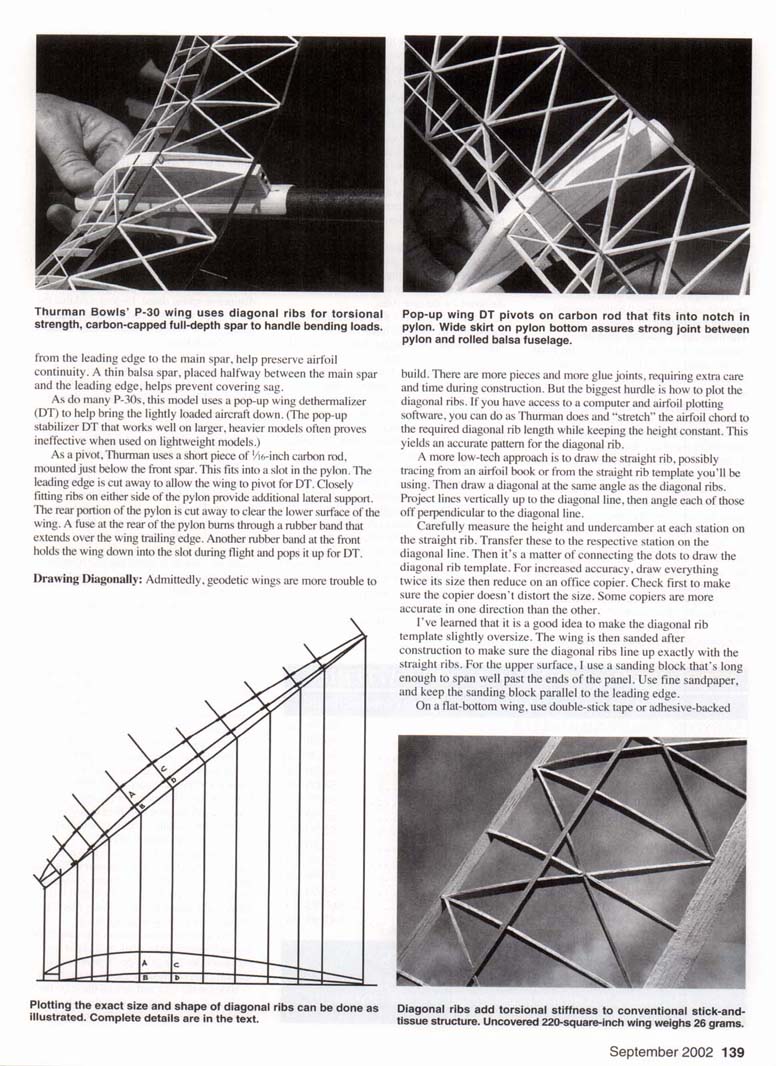
One modeler who has been exploring new variations on diagonal-rib construction is Thurman Bowles of Florida. His latest P-30 combines balsa and carbon fiber to yield a thin, lightweight wing that's surprisingly stiff. The full-depth spar is 1/16-inch balsa, capped with .003-inch carbon fiber top and bottom. The carbon fiber adds a good deal of strength in bending since the carbon is at the extreme top and bottom of the spar. (In any type of beam, the highest loads are at the top and bottom—not in the middle. That's why steel beams are made in an I or H shape.)
Although it looks like a solid piece of carbon fiber, the P-30's trailing edge is actually a carbon-balsa-carbon sandwich. This not only saves weight, but it allows a slightly thicker trailing edge to be used. In addition, the .003-inch-thick carbon fiber that Thurman uses is easier to cut than the .020-inch-thick carbon typically used for solid-carbon trailing edges. The thin carbon can be cut with a single pass of a sharp knife; the thicker stuff is best cut with a special diamond blade in a table saw.
The balsa straight ribs are widely spaced, allowing room for crossing diagonal ribs aft of the full-depth spar. At the front, the diagonal ribs meet at the balsa leading edge. False ribs, running from the leading edge to the main spar, help preserve airfoil continuity. A thin balsa spar, placed halfway between the main spar and the leading edge, helps prevent covering sag. As do many P-30s, this model uses a pop-up wing dethermalizer (DT) to help bring the lightly loaded aircraft down. (The pop-up stabilizer DT that works well on larger, heavier models often proves ineffective when used on lightweight models.)
As a pivot, Thurman uses a short piece of 1/16-inch carbon rod, mounted just below the front spar. This fits into a slot in the pylon. The leading edge is cut away to allow the wing to pivot for DT. Closely fitting ribs on either side of the pylon provide additional lateral support. The rear portion of the pylon is cut away to clear the lower surface of the wing. A fuse at the rear of the pylon burns through a rubber band that extends over the wing trailing edge. Another rubber band at the front holds the wing down into the slot during flight and pops it up for DT.
Drawing Diagonally:
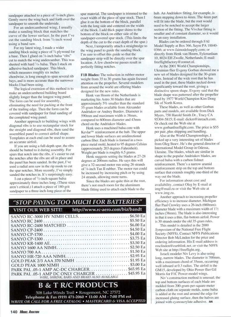
Admittedly, geodetic wings are more trouble to build. There are more pieces and more glue joints, requiring extra care and time during construction. But the biggest hurdle is how to plot the diagonal ribs. If you have access to a computer and airfoil-plotting software, you can do as Thurman does and "stretch" the airfoil chord to the required diagonal rib length while keeping the height constant. This yields an accurate pattern for the diagonal rib.
A more low-tech approach is to draw the straight rib, possibly tracing from an airfoil book or from the straight-rib template you'll be using. Then draw a diagonal at the same angle as the diagonal ribs. Project lines vertically up to the diagonal line, then angle each of those perpendicular to the diagonal line.
Carefully measure the height and undercamber at each station on the straight rib. Transfer these to the respective station on the diagonal line. Then it's a matter of connecting the dots to draw the diagonal rib template. For increased accuracy, draw everything twice its size then reduce on an office copier. Check first to make sure the copier doesn't distort the size. Some copiers are more accurate in one direction than the other.
I've learned that it is a good idea to make the diagonal rib template slightly oversize. The wing is then sanded after construction to make sure the diagonal ribs line up exactly with the straight ribs. For the upper surface, I use a sanding block that's long enough to span well past the ends of the panel. Use fine sandpaper, and keep the sanding block parallel to the leading edge.
On a flat-bottom wing, use double-stick tape or adhesive-backed sandpaper attached to a piece of 1/4-inch glass. Gently move the wing back and forth over the sandpaper to smooth the underside.
For an undercambered wing, I usually make a sanding block that matches the curve of the lower surface. In the past I've cut the sanding block from 3/4-inch wood using a band saw.
For my latest wing, I made a wider sanding block using a piece of 3/4-inch plywood for a base. Then I glued on 1/16-inch balsa "ribs" cut to match the wing undercamber. This was sheeted with hard 1/16-inch balsa. Then I stuck on adhesive-backed sandpaper. This block, which measures roughly six inches chordwise, is long enough to span several rib bays, and is more accurate than the narrower blocks I had been using.
The logical extension of this method is to make an undercambered building board slightly longer than the longest wing panel. The form can be used for assembly, eliminating the need for packing at the front of the trailing edge. Then the form can be covered with sandpaper for final sanding of the completed wing panel.
Another approach to building wings with diagonal ribs is to use rectangular stock for the straight and diagonal ribs, then sand the assembled panel to the correct airfoil shape. Templates at each end can be used to assure an accurate airfoil.
If you are using a full-depth spar, the ribs should be butted to it during assembly. For spars that notch into the ribs, it's easier to cut the notches after the ribs are all in place and the panel has been sanded. In the past, I've used a radial-arm saw in the rip mode to cut the spar notches. More recently, I've simply sanded the notches in. It's surprisingly easy.
I cut a piece of 1/2-inch-square balsa approximately three inches long (these sizes aren't critical). I attach a piece of 180-grit sandpaper to a three-inch-long piece of spar material. The sandpaper is trimmed to the exact width of the piece of spar stock, then glued to the bottom of the block, parallel with the long side and centered on the width of the block. I add thick paper shims to the bottom of the block on either side of the sandpaper-covered spar stock to limit the depth of the cut to the exact depth of the spar.
Next, I temporarily attach a straightedge to the wing panel to guide the sanding block. I'm sure to offset this guide so that the sandpaper strip will be directly over the spar location. A few chordwise passes result in perfectly fitting notches.
F1B Blades
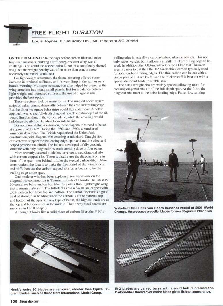
The reduction in rubber-motor weight from 35 to 30 grams has again focused attention on the propeller. Several modelers from around the world are offering blades designed for the new rules.
Henk van Hoorn of the Netherlands is marketing his Astro 30 blades that are approximately 5% smaller than the standard 35-gram blades available from Alexander Andriukov or Andrey Burdov. Diameter is 590 mm and maximum width is 38 mm, compared to 600 mm diameter and 43 mm chord on the Andriukov blades.
Henk uses a machined balsa core with Kevlar reinforcement at the hub. The upper and lower blade surfaces are unidirectional carbon fiber. Each blade is formed in a two-piece metal mold, heated to 95° Celsius (approximately 203° Fahrenheit). Weight per blade is roughly 5 grams.
Henk suggests setting the blades at 27–28° at 200 mm radius. He says this will give a 32-second motor run using 26 strands of 1/8-inch Tan II rubber. The motor run could be increased by increasing pitch or by using 24 strands, allowing more turns.
Since the blades are quite thin at the root, there's not much room for the aluminum hub fitting used to attach each blade to the hub. An Andriukov fitting, for example, is 6 mm stepping down to 4 mm. The 4 mm part will fit into the blade, but the root would need to be notched to accept the larger section of the fitting. The Vivchar fitting is smaller and of constant diameter, so it would be an easy installation.
Ordering/contact information for Henk van Hoorn:
- FAI Model Supply, Box 366, Sayre PA 18840-0366; www.faimodelsupply.com
- Henk van Hoorn, Eykmanlaan 10, 8204 EN Zwolle, Netherlands; E-mail: [email protected]
At the 2001 World Championships, Ukrainian flier Evgeny Gorban showed me a new set of blades designed for the 30-gram rules. Instead of the wide root that he has used in the past, these blades neck down significantly toward the root, giving a distinctive spoon shape. Evgeny said that the blade shape was patterned after the propeller used by 1977 World Champion Kim Dong Sik of North Korea.
These blades, as well as other Gorban parts and models, are available from:
- Dick Myers, 758 Harold Smith Dr., Tracy CA 95304-5815; E-mail: [email protected]
- Web: www.gorbanfreeflight.com
Price: $55 per pair, plus shipping and handling.
Also at the World Championships, I picked up a very interesting set of blades from Oleg Stoev. He's the general director of International Model Group in Odessa, Ukraine. The blades, which are similar in shape to the popular Andriukov blades, are carbon reinforced with a carbon-fiber reinforcement strip on the bottom surface that extends roughly one-third of the way out the blade.
For information about cost and availability, contact:
- Oleg Stoev, International Model Group, E-mail: [email protected]; Web: www.img.ru
Another approach to increasing propeller efficiency is to increase diameter. Michigan flier Paul Crowley uses a 26-inch (660 mm) diameter blade with a maximum width of 1-1/2 inches (38 mm). The blade is also interesting in that it uses a thin, flat-bottom airfoil. Power was 30 strands under the old 35-gram rules. This model is detailed in the 2000 Symposium of the National Free Flight Society (NFFS). Contact NFFS Publications Director Bob McLinden for price and ordering information:
- E-mail: [email protected]
- Web: www.freeflight.org
Israeli modeler Niv Levy is also using long, narrow blades. The diameter is 700 mm, with a maximum chord of 35 mm occurring at 0.3 radius. The blades are made of balsa with a carbon-fiber reinforcement strip on the bottom surface only. They have been used to good effect by Ohio Power flier Gil Morris for F1C Power-model wings.
Niv's construction method is unusual: the top and bottom surfaces of each blade are molded from thin (200-gram-per-square-meter) carbon-fiber cloth on separate molds. Some balsa is then added at the root and around the edge for increased gluing surface, and the halves are joined with cyanoacrylate adhesive.
Transcribed from original scans by AI. Minor OCR errors may remain.

