
FREE FLIGHT DURATION
Louis Joyner 183 Civitas St., Mt. Pleasant SC 29464
Try a little turbulence
At the narrow wing chords and slow flying speeds of most nongas Free Flight (FF) models, the wing airfoils usually need some sort of turbulation on the upper surface for maximum performance.
The purpose of this turbulation is to help keep the thin boundary layer attached to the upper surface of the wing, allowing the wing to fly at a higher angle of attack without stalling.
Almost any type of surface roughness or bumps will provide turbulence of some sort. It may not be optimum, but it may be better than nothing at all. (It could also be worse than nothing, but more about that later.)
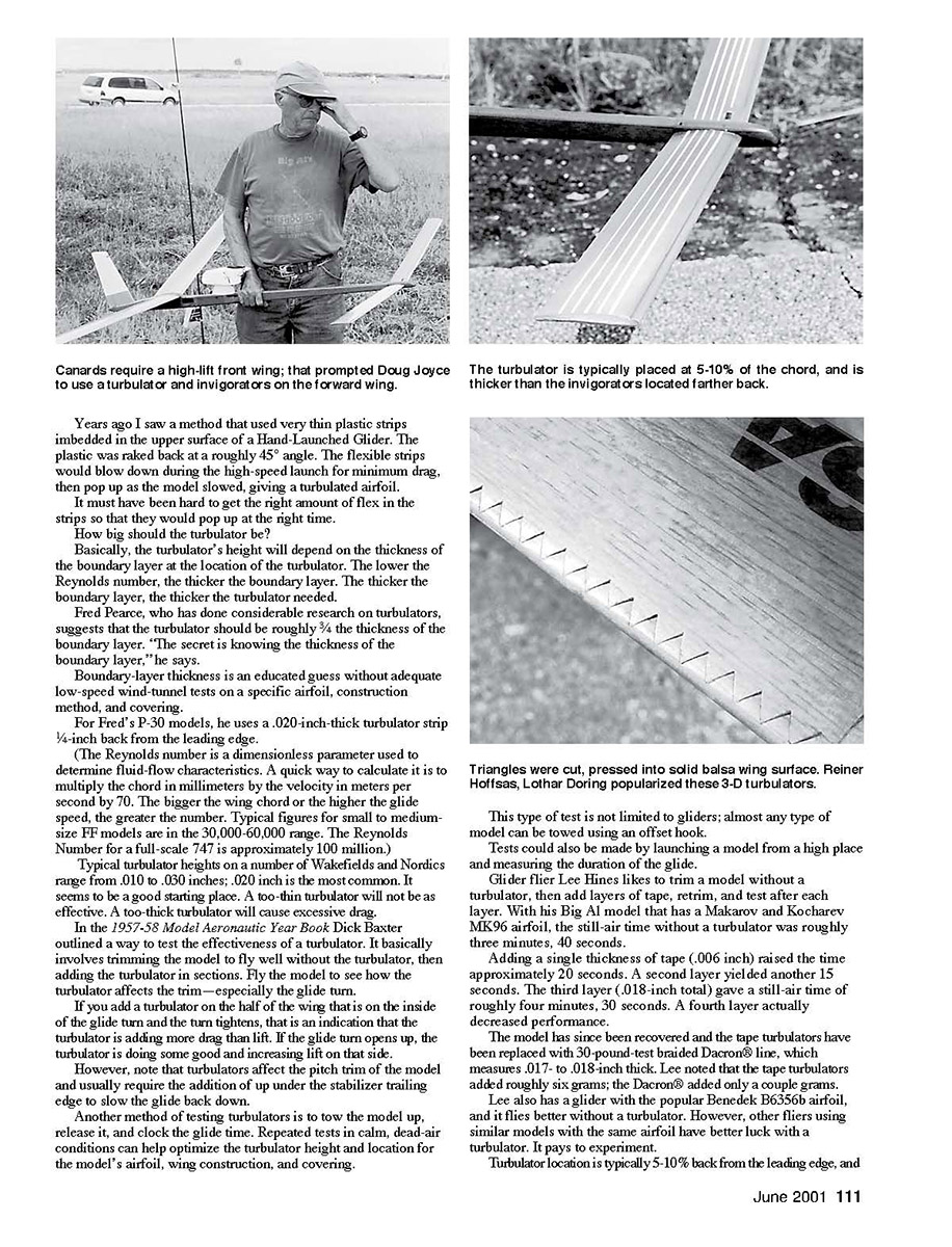
The multispar wing construction that Chet Lanzo and Dick Korda popularized in the late 1930s is an example of a "stealth" turbulator that is legal for Old-Timer events.
(Adding a thread turbulator is not allowed if one is not shown on the plans. Since the thread turbulators didn't seem to come into use until the 1950s, they weren't included on the pre-World War II model plans.)
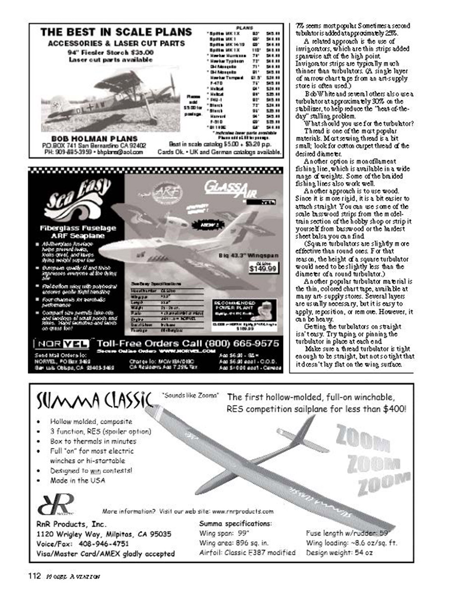
Turbulators are rarely seen on Power models; at the high climb speeds, a turbulator would cause too much drag and reduce climb height. And gas models tend to have less highly cambered wing airfoils, glide at higher speeds, and have wider wing chords, so there is less need for turbulation.
The late Tom McLaughlin suggested using a retractable turbulator for F1C Power. He never got around to trying it in practice, but he did mention some sort of inflatable strip that would work similar to the deicer boot on some full‑scale aircraft.
Another approach Tom was thinking about used a rotating strip that would lay flush during the climb, then rotate up for the glide. It seems that retractable turbulators would be easier to rig up mechanically than flaps. Has anyone played around with the idea?
Years ago I saw a method that used very thin plastic strips embedded in the upper surface of a hand‑launched glider. The plastic was raked back at a roughly 45° angle. The flexible strips would blow down during the high‑speed launch for minimum drag, then pop up as the model slowed, giving a turbulated airfoil. It must have been hard to get the right amount of flex in the strips so that they would pop up at the right time.
How big should the turbulator be?
Basically, the turbulator's height will depend on the thickness of the boundary layer at the location of the turbulator. The lower the Reynolds number, the thicker the boundary layer. The thicker the boundary layer, the thicker the turbulator needed.
Fred Pearce, who has done considerable research on turbulators, suggests that the turbulator should be roughly 3/4 the thickness of the boundary layer. "The secret is knowing the thickness of the boundary layer," he says. Boundary‑layer thickness is an educated guess without adequate low‑speed wind‑tunnel tests on a specific airfoil, construction method, and covering. For Fred's P‑30 models, he uses a .020‑inch‑thick turbulator strip 1/4 inch back from the leading edge.
(The Reynolds number is a dimensionless parameter used to determine fluid‑flow characteristics. A quick way to calculate it is to multiply the chord in millimeters by the velocity in meters per second by 70. The bigger the wing chord or the higher the glide speed, the greater the number. Typical figures for small to medium‑size FF models are in the 30,000–60,000 range. The Reynolds number for a full‑scale 747 is approximately 100 million.)
Typical turbulator heights on a number of Wakefields and Nordics range from .010 to .030 inches; .020 inch is the most common. It seems to be a good starting place. A too‑thin turbulator will not be as effective. A too‑thick turbulator will cause excessive drag.
Testing turbulators
In the 1957–58 Model Aeronautic Year Book Dick Baxter outlined a way to test the effectiveness of a turbulator. It basically involves trimming the model to fly well without the turbulator, then adding the turbulator in sections.
- Fly the model to see how the turbulator affects the trim—especially the glide turn.
- Add a turbulator on the half of the wing that is on the inside of the glide turn and observe:
- If the turn tightens, the turbulator is adding more drag than lift.
- If the glide turn opens up, the turbulator is doing some good and increasing lift on that side.
Note that turbulators affect the pitch trim of the model and usually require the addition of up elevator or adjustment of the stabilizer trailing edge to slow the glide back down.
Another method of testing turbulators is to tow the model up, release it, and clock the glide time. Repeated tests in calm, dead‑air conditions can help optimize the turbulator height and location for the model’s airfoil, wing construction, and covering.
This type of test is not limited to gliders; almost any type of model can be towed using an offset hook. Tests could also be made by launching a model from a high place and measuring the duration of the glide.
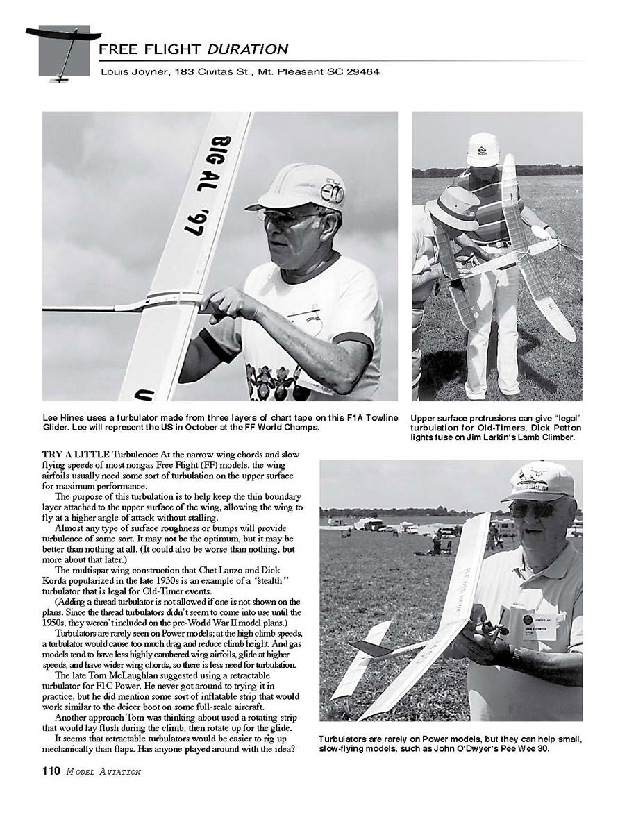
Glider flier Lee Hines likes to trim a model without a turbulator, then add layers of tape, retest, and test after each layer. With his Big Al model that has a Makarov and Kocharov MK96 airfoil, the still‑air time without a turbulator was roughly 3 minutes 40 seconds.
- Adding a single thickness of tape (.006 inch) raised the time approximately 20 seconds.
- A second layer yielded another 15 seconds.
- The third layer (.018‑inch total) gave a still‑air time of roughly 4 minutes 30 seconds.
- A fourth layer actually decreased performance.
The model has since been recovered and the tape turbulators have been replaced with 30‑pound‑test braided Dacron® line, which measures .017 to .018 inch thick. Lee noted that the tape turbulators added roughly six grams; the Dacron® added only a couple grams.
Lee also has a glider with the popular Benedek B6356b airfoil, and it flies better without a turbulator. However, other fliers using similar models with the same airfoil have better luck with a turbulator. It pays to experiment.
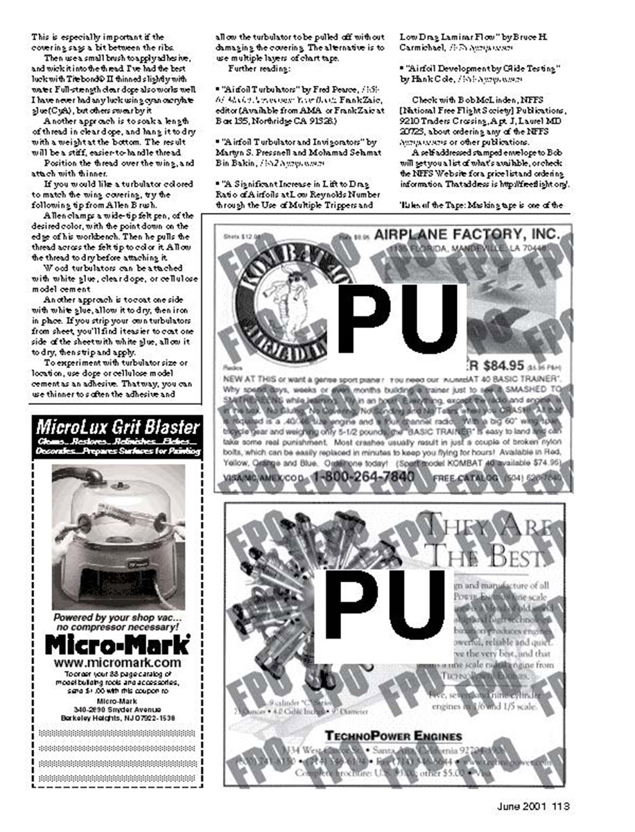
Turbulator location is typically 5–10% back from the leading edge, and the turbulator is usually thicker than the invigorator or located farther back.
June 2001
Turbulator placement and related devices
Fly the model with the turbulator in place at each stage.
Sometimes a second turbulator is added to approximately 25% chord.
A related approach is the use of invigorators, which are thin strips added spanwise aft of the high point. Invigorator strips are typically much thinner than turbulators. A single layer of narrow chart tape from an art‑supply store is often used.
Bob White and several others also use a turbulator at approximately 30% on the stabilizer, to help reduce the "beat‑of‑the‑day" stalling problem.
What to use for the turbulator
Thread is one of the most popular materials. Most sewing thread is a bit small; look for cotton carpet thread of the desired diameter.
Another option is monofilament fishing line, which is available in a wide range of weights. Some braided fishing lines also work well.
Wood is another approach. Since it is more rigid, it is a bit easier to attach straight. You can use scale basswood strips from the model‑train section of the hobby shop or strip it yourself from basswood or the hardest balsa you can find.
- Square turbulators are slightly more effective than round ones. For that reason, the height of a square turbulator would need to be slightly less than the diameter of a round turbulator.
- Thin, colored chart tape (available at many art‑supply stores) is a popular turbulator material. Several layers are usually necessary, but it is easy to apply, reposition, or remove. However, it can be heavy.
Getting the turbulators on straight is easy. Try taping or pinning the turbulator in place at each end.
Make sure a thread turbulator is tight enough to be straight, but not so tight that it doesn't lay flat on the wing surface. This is especially important if the covering spans a bit between the ribs.
One method is to brush on adhesive and wick it into the seam. The author has had the best luck with TriBond 1100 thinned slightly with water. Full‑strength cyanoacrylate also works well for some. Another approach is to soak a length of thread in a stiffening solution and hang it to dry with a weight at the bottom; the result will be a stiff, easier‑to‑handle thread. Position the thread over the wing, and attach with thinner.
If you would like a turbulator colored to match the wing covering, try this tip from Allen Brush: clamp a wide‑tip felt pen of the desired color with the point down on the edge of the workbench, then pull the thread across the felt tip to color it. Allow the thread to dry before attaching it.
Wood turbulators can be attached with white glue, clear dope, or cellulose model cement. Another approach is to coat one side with white glue, allow it to dry, then iron it in place. If you strip your own turbulators from sheet you’ll find it easier to coat one side of the sheet with white glue, allow it to dry, then strip into spars.
To experiment with turbulator size or location, use dope or cellulose model cement as an adhesive. That way, you can use thinner to soften the adhesive and allow the turbulator to be pulled off without damaging the covering. The alternative is to use multiple layers of chart tape.
Further reading
- "Airfoil Turbulators" by Fred Pearce, Jr. (See "Model Airplane News," Nov./Dec., Frank Zaic, editor). (Available from AMA or Frank Zaic at P.O. Box 1365, Northridge CA 91328.)
- "Airfoil Turbulator and Investigations" by Martyn S. Preenell and Mohamed Schmitt Bin Bakin (text unclear in scan).
- "A Significant Increase in Lift to Drag Ratio of Airfoils at Low Reynolds Number through the Use of Multiple Trippers and Low Drag Laminar Flow" by Bruce H. Carmichael (text unclear in scan).
- "Airfoil Development by Glide Testing" by Hank Cade (text unclear in scan).
Check with Bob McLinden, NFFS (National Free Flight Society) Publications, 9210 Traders Crossing, Apt. J, Laurel MD 20708, about ordering any of the NFFS publications or other publications. A self‑addressed stamped envelope to Bob will get you a list of what's available, or check the NFFS web site for postal ordering information: http://nffsonline.org.
Transcribed from original scans by AI. Minor OCR errors may remain.

