
FREE FLIGHT DURATION
Louis Joyner, 183 Civitas St., Mt. Pleasant SC 29464
WITH ALL the interest in high-tech carbon-fiber structures, it's easy to overlook some of the basics of building with balsa.
In the past, balsa was almost always paired with tissue to create that familiar stick-and-tissue construction. Structurally, the tissue was an important partner in creating lightweight, yet stiff structures.
Stretched tight and given a few coats of dope, tissue would provide surprising torsional rigidity to a somewhat floppy balsa structure.
The problem came on misty mornings or rainy afternoons, when the damp tissue loosened and sagged. Rubber-model fuselages would twist alarmingly under a full wound motor. Power models would go off-pattern as wings flexed in flight. And between flying sessions (and often between flights), model parts would move slightly with changes in humidity.
Trimming was a never-ending process.
Pairing a traditional balsa structure with a more waterproof plastic covering usually doesn't help. The thinner plastic films, such as clear Mylar™, offer very little strength compared to tight tissue covering.
Through the years, various methods have been developed to increase rigidity—especially torsional rigidity—in balsa structures. Sheet-balsa D-boxes and fully sheeted wings provide the necessary strength, but with a marked increase in weight.
Multi-spar construction, especially when paired with closely spaced ribs, divided a wing into small rectangles, which were less affected by the changes in tissue tension.
Balancing the spar locations top and bottom could also reduce the tendency of a wing or stabilizer to bow up or down after covering. (Flat-bottomed wings with the spar on the bottom are especially prone to bowing upward, since all the compressive strength is along the bottom surface.)
Perhaps the best way to give a balsa-and-tissue wing or tail extra torsional strength is by putting some—or even all—of the ribs at an angle. Called geodetic construction, this method was popular in Great Britain and Italy in the 1950s, but found only limited acceptance in this country.
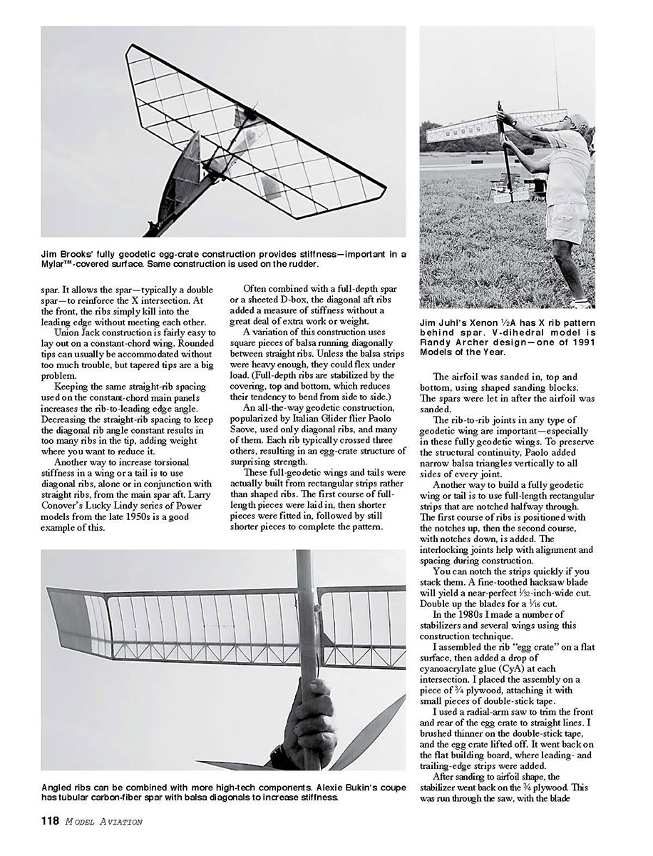
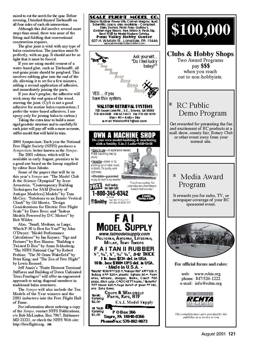
The British method, aptly named the Union Jack after its resemblance to the flag, utilizes a mix of normal fore-and-aft "straight" ribs and diagonal ribs. The straight ribs are typically placed slightly wider apart than with normal construction.
The diagonals are arranged in an X pattern between the straight ribs. The angle formed by the diagonal ribs is important. For maximum rigidity, they should be set at roughly 30–40° to the leading edge.
Extra straight ribs are often added from the center of the X, to provide extra support to the leading edge and the trailing edge.
A variation of the Union Jack made popular by Bob White shifts the center of the X from the middle of the wing chord forward to the airfoil high point—usually at approximately 30% chord. That way, the diagonals intersect at the spar. It allows the spar—typically a double spar—to reinforce the X intersection. At the front, the ribs simply keel into the leading edge without meeting each other.
Union Jack construction is fairly easy to lay out on a constant-chord wing. Rounded tips can usually be accommodated without too much trouble, but tapered tips are a big problem. Keeping the same straight-rib spacing used on the constant-chord main panels increases the rib-to-leading-edge angle. Decreasing the straight-rib spacing to keep the diagonal rib angle constant results in too many ribs in the tip, adding weight where you want to reduce it.
Another way to increase torsional stiffness in a wing or a tail is to use diagonal ribs, alone or in conjunction with straight ribs, from the main spar aft. Larry Conover's Lucky Lindy series of power models from the late 1950s is a good example of this.
Often combined with a full-depth spar or a sheeted D-box, the diagonal aft ribs added a measure of stiffness without a great deal of extra work or weight.
A variation of this construction uses square pieces of balsa running diagonally between straight ribs. Unless the balsa strips were heavy enough, they could flex under load. (Full-depth ribs are stabilized by the covering, top and bottom, which reduces their tendency to bend from side to side.)
An all-the-way geodetic construction, popularized by Italian glider flier Paolo Saove, used only diagonal ribs, and many of them. Each rib typically crossed three others, resulting in an egg-crate structure of surprising strength.
These full-geodetic wings and tails were actually built from rectangular strips rather than shaped ribs. The first course of full-length pieces were laid in, then shorter pieces were fitted in, followed by still shorter pieces to complete the pattern.
The airfoil was sanded in, top and bottom, using shaped sanding blocks. The spars were left in after the airfoil was sanded.
The rib-to-rib joints in any type of geodetic wing are important—especially in these fully geodetic wings. To preserve the structural continuity, Paolo added narrow balsa triangles vertically to all sides of every joint.
Another way to build a fully geodetic wing or tail is to use full-length rectangular strips that are notched halfway through. The first course of ribs is positioned with the notches up, then the second course, with notches down, is added. The interlocking joints help with alignment and spacing during construction.
You can notch the strips quickly if you stack them. A fine-toothed hacksaw blade will yield a near-perfect 1/32-inch-wide cut. Double up the blades for a 1/16-inch cut.
In the 1980s I made a number of stabilizers and several wings using this construction technique.
I assembled the rib "egg crate" on a flat surface, then added a drop of cyanoacrylate glue (CyA) at each intersection. I placed the assembly on a piece of 3/4-inch plywood, attaching it with small pieces of double-stick tape.
I used a radial-arm saw to trim the front and rear of the egg crate to straight lines. I brushed thinner on the double-stick tape, and the egg crate lifted off. It went back on the flat building board, where leading- and trailing-edge strips were added.
After sanding to airfoil shape, the stabilizer went back on the 3/4-inch plywood. This was run through the saw, with the blade.
Transcribed from original scans by AI. Minor OCR errors may remain.

