
David Sechrist's F1G Coupe
by Louis Joyner [email protected]
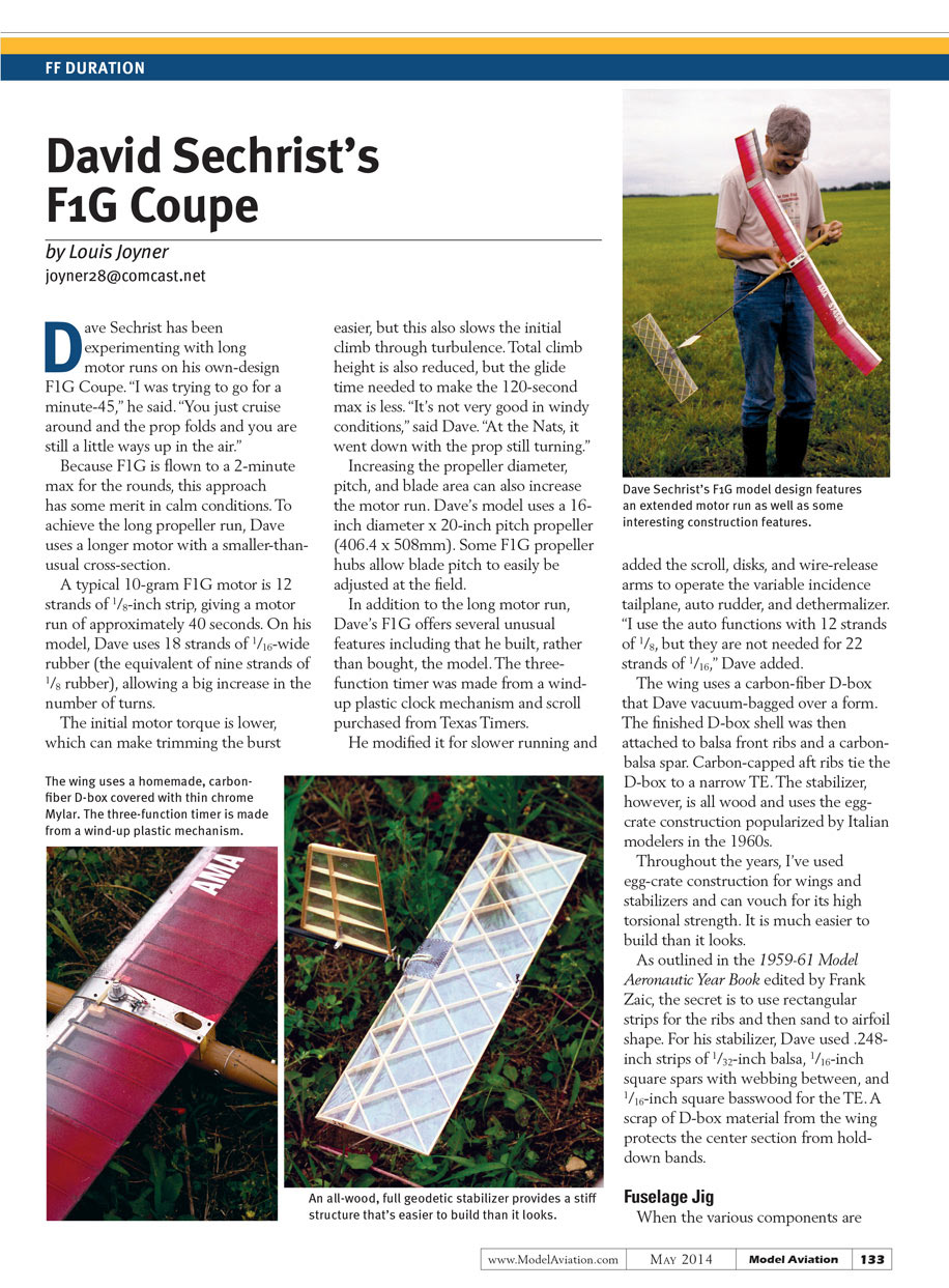
Dave Sechrist has been experimenting with long motor runs on his own-design F1G Coupe. "I was trying to go for a minute-45," he said. "You just cruise around and the prop folds and you are still a little ways up in the air."
Because F1G is flown to a 2-minute max for the rounds, this approach has some merit in calm conditions. To achieve the long propeller run, Dave uses a longer motor with a smaller-than-usual cross-section.
Motor
A typical 10-gram F1G motor is 12 strands of 1/8-inch strip, giving a motor run of approximately 40 seconds. On his model, Dave uses 18 strands of 1/16-inch-wide rubber (the equivalent of nine strands of 1/8-inch rubber), allowing a big increase in the number of turns.
The initial motor torque is lower, which can make trimming the burst easier, but this also slows the initial climb through turbulence. Total climb height is also reduced, but the glide time needed to make the 120-second max is less. "It's not very good in windy conditions," said Dave. "At the Nats, it went down with the prop still turning."
Increasing the propeller diameter, pitch, and blade area can also increase the motor run.
Propeller
Dave's model uses a 16-inch-diameter x 20-inch-pitch propeller (406.4 x 508 mm). Some F1G propeller hubs allow blade pitch to be easily adjusted at the field.
Timer and control functions
In addition to the long motor run, Dave's F1G offers several unusual features, including that he built, rather than bought, the model. The three-function timer was made from a wind-up plastic clock mechanism and scroll purchased from Texas Timers. He modified it for slower running and added the scroll, disks, and wire-release arms to operate the variable-incidence tailplane, auto rudder, and dethermalizer. "I use the auto functions with 12 strands of 1/8, but they are not needed for 22 strands of 1/16," Dave added.
Wing and stabilizer construction
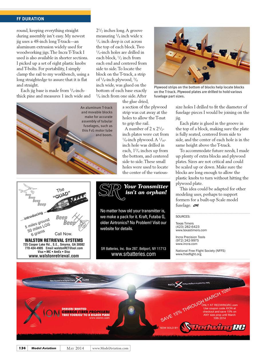
The wing uses a carbon-fiber D-box that Dave vacuum-bagged over a form. The finished D-box shell was then attached to balsa front ribs and a carbon-balsa spar. Carbon-capped aft ribs tie the D-box to a narrow trailing edge. The stabilizer, however, is all-wood and uses the egg-crate construction popularized by Italian modelers in the 1960s.
Throughout the years, I've used egg-crate construction for wings and stabilizers and can vouch for its high torsional strength. It is much easier to build than it looks.
As outlined in the 1959–61 Model Aeronautic Year Book edited by Frank Zaic, the secret is to use rectangular strips for the ribs and then sand to airfoil shape. For his stabilizer, Dave used .248-inch-high strips of 1/32-inch balsa, 1/16-inch square spars with webbing between, and 1/16-inch square basswood for the trailing edge. A scrap of D-box material from the wing protects the center section from hold-down bands.
Fuselage Jig
When the various components are round, keeping everything straight during assembly isn't easy. My newest jig uses a 48-inch-long T-track—an aluminum extrusion widely used for woodworking jigs. The Incra T-track I used is also available in shorter sections. I picked up a set of eight plastic knobs and T-bolts. For portability, I simply clamp the rail to my workbench, using a long straightedge to assure that it is flat and straight.
Each jig base is made from 3/4-inch-thick pine and measures 1 inch wide and 2 1/2 inches long. A groove measuring 1/8 inch wide x 1/4 inch deep is cut across the top of each block. Two 1/4-inch holes are drilled in each block, 1/2 inch from each end and centered from side to side. To locate the block on the T-track, a strip of 1/8-inch plywood, 3/8 inch wide, was glued on the bottom of each base exactly 3/8 inch from one side. After the glue dried, a section of the plywood strip was cut away at the holes to allow the T-nut to grip the rail.
A number of 2 inch x 2 1/2 inch plates were cut from 1/8-inch plywood. A 1/16-inch hole was drilled in each, 1 3/4 inches up from the bottom and centered side to side. These small holes were used to locate the center of the various-size holes I drilled to fit the diameter of fuselage pieces I would be joining on the jig.
Each plate is glued in the groove in the top of a block, making sure the plate is fully seated, centered from side to side, and that the center of each hole is the same height above the T-track.
To accommodate future needs, I made up plenty of extra blocks and plywood plates. Sizes are not critical and could be scaled up or down. Make sure the blocks are long enough to allow the plastic knobs to turn without hitting the plywood plate.
This idea could be adapted for other modeling uses, perhaps to support formers for a built-up scale model fuselage.
Sources
- Texas Timers
(423) 282-6423 www.texastimers.com
- Incra Precision Tools
(972) 242-9975 www.incra.com
- National Free Flight Society (NFFS)
Transcribed from original scans by AI. Minor OCR errors may remain.

