
Perfect pitch
by Louis Joyner [email protected]
For any rubber-powered model, the propeller is one of the most important components. For maximum duration, it is vital that the propeller be carefully matched to the rubber motor and that both are suited to the model and to the way it needs to be flown.
For example, the motor and/or propeller can be altered to increase motor run for calm-air flying, or to shorten the motor run to speed up the climb and get through ground turbulence in windy conditions. Typical changes include:
- Reducing motor cross-section (fewer strands) or increasing propeller pitch to increase motor run.
- Increasing motor cross-section or decreasing pitch to shorten motor run and give a faster initial climb.
For some events such as P-30, propeller choices are slightly limited, but even among commercially made plastic propellers there are variations in pitch. For many other rubber events, pitch as well as diameter, blade width, and blade shape are unregulated, allowing wide latitude in propeller design.
Because pitch is the easiest propeller parameter to change in the field, models often feature hubs with fittings that allow propeller pitch to be adjusted on the ground. This is not the same as the variable-pitch hubs frequently used on F1B and F1G models to change pitch during the motor run; those systems typically decrease pitch as torque drops off.
What is pitch?
Pitch is the theoretical distance a propeller would move forward in one revolution. Pitch is typically measured at 67% to 75% of the propeller radius. Knowing the blade angle and the circumference at the chosen radius, you can determine pitch graphically or with a calculator.
Formula: P = Tan(A) × 2πr
- P is pitch
- A is the blade angle
- r is the local radius
Example: a 600 mm diameter propeller (radius 300 mm) with a blade angle of 30° measured at 0.7 radius (210 mm): P = 0.57735 × 2 × 3.1416 × 210 mm = 761.80 mm.
It only takes a slight difference in blade angle to make a significant difference in pitch. In the example above, an increase of 1° in blade angle increases pitch by 31.02 mm (about 13/16 inch, or slightly more than 4%). Thus it is important that both blades be accurately set to the desired angle.
Measuring and setting blade angles
Common methods for setting blade angle:
- Adjustable angle finder or protractor set at a specific radius.
- A set of fixed angled gauges sized to the chosen radius.
- A fixed-angle gauge (for example, 30°) moved in or out from the hub to change effective radius — this works for helical-pitch propellers but not for modern designs with varying pitch at different radial stations (pitch may be lower near the hub, increase to a maximum around 70% radius, then decrease toward the tip).
Many rubber fliers prefer fixed angled gauges for repeatability.
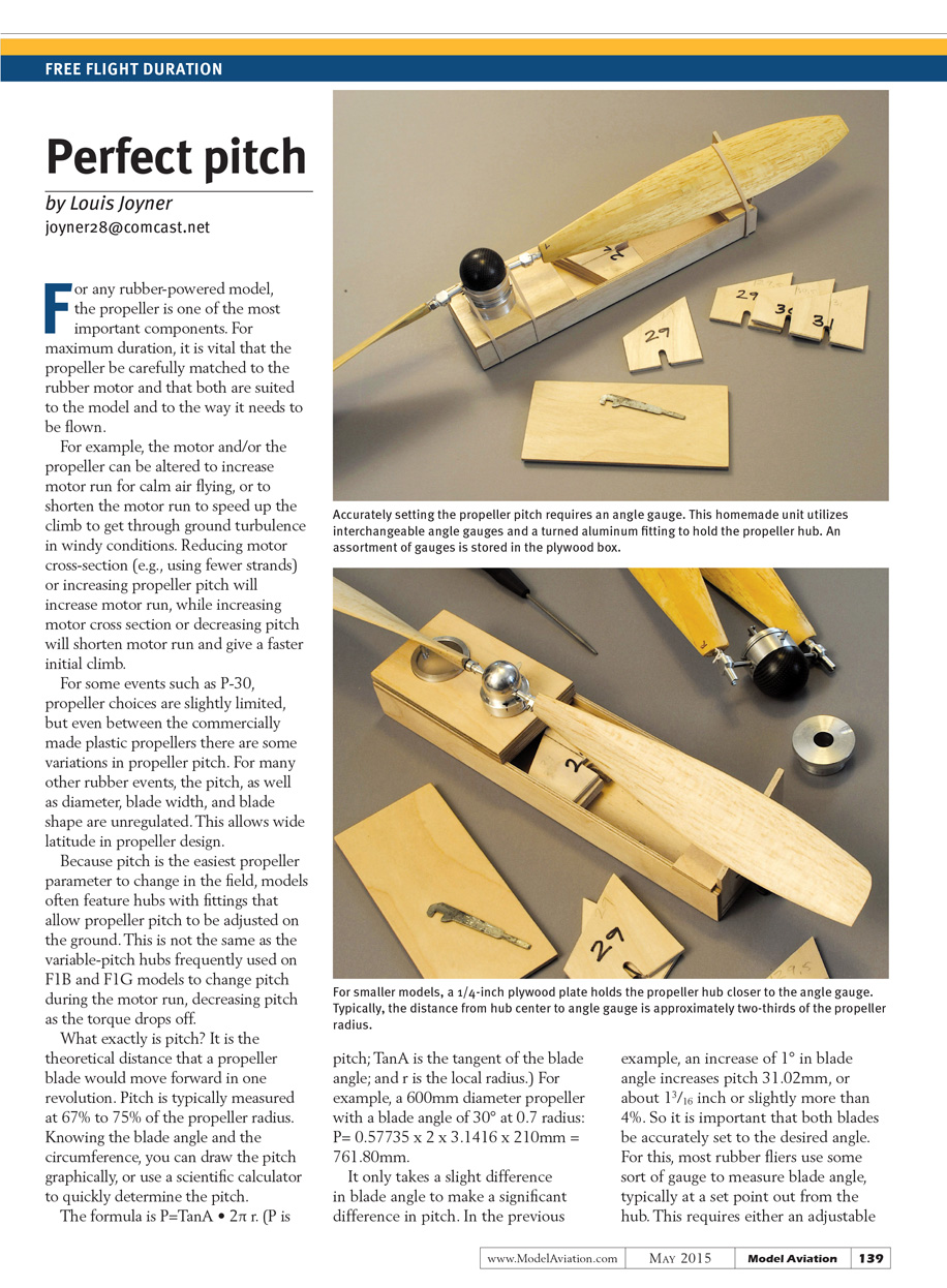
Blade-angle jig (my method)
To measure and set blade angles I made a jig with a range of angle gauges that can be easily swapped. This offers better repeatability than a single adjustable angle with a degree scale.
Materials and general design:
- Small box made from 1/8-inch birch plywood.
- Turned aluminum fitting to hold the propeller hub (an extra fitting for different hub types stored in the box).
- Series of angle gauges made from 1/8-inch plywood, stored inside the box along with a small wrench.
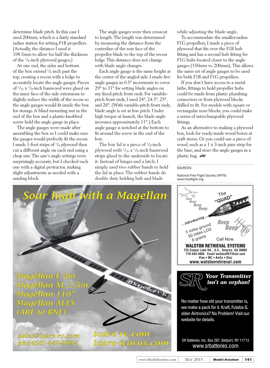
- Pieces of 1/32 × 1/8-inch basswood glued over the ledge to hold the gauges in position and to protect the top edge of the box.
Box dimensions I used (not critical): 9 inches long × 2.25 inches wide × 1 inch deep. What is critical is the distance from the center of the hub-holding fitting to the end of the box — this determines the radius used to set blade pitch. I used 200 mm (actually 198.5 mm to allow for half the thickness of the 1/8-inch plywood gauges), a common radius station for setting F1B propellers.
Construction of the angle gauges:
- Made 1-foot strips of 1/8-inch plywood, cut different angles on each end with a chop saw.
- Verified each angle with a digital protractor and fine-tuned with a sanding block as needed.
- Crosscut the angled strips to length. Length was determined by measuring from the centerline of the rear face of the propeller blade to the top of the recess ledge (this distance does not change when blade angle changes).
- Each gauge is the same height at the center of the angled side and is notched at the bottom to fit around the screw in the end of the box.
Gauges I made:
- Five gauges in 0.5° increments to cover 29° to 31° for setting blade angles on fixed-pitch front ends.
- For variable-pitch front ends I used 24°, 24.5°, 25°, and 26°. (With variable-pitch front ends, blade angle is set at the low pitch; under high torque at launch the blade angle typically increases by about 11°.)
Box lid and clamping:
- Lid is 1/8-inch plywood with 1/16 × 1/8-inch basswood strips glued to the underside to locate it.
- Instead of hinges and a latch, two rubber bands hold the lid in place and also serve to hold the hub and blade while adjusting blade angle.
Accommodating other propeller sizes:
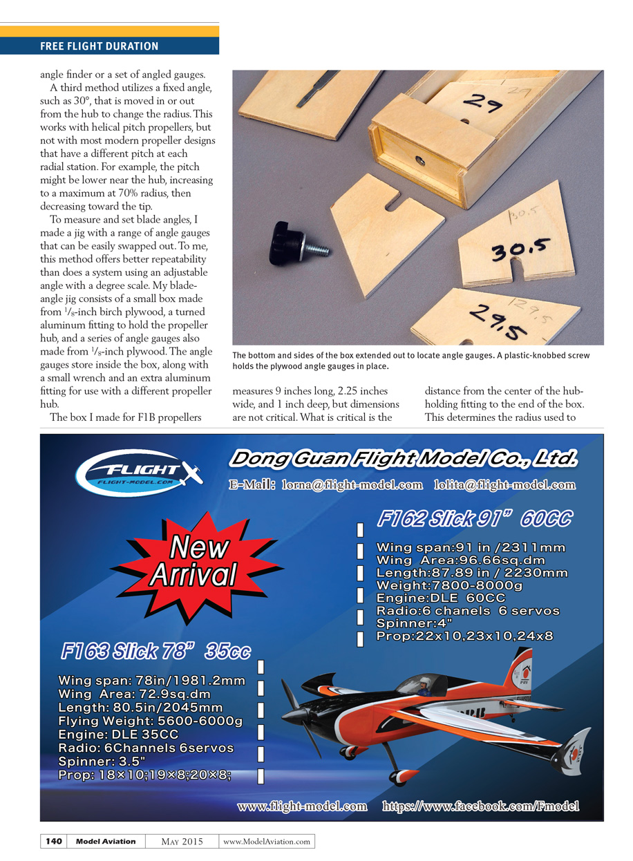
- To handle smaller-radius F1G propellers, I made a plywood adapter that fits over the F1B hub fitting and provides a second hub fitting located closer to the angle gauges (150 mm vs. 200 mm). This allows the same set of angle gauges to be used for both F1B and F1G.
Alternatives if you lack a lathe:
- Make hub fittings from plastic plumbing connectors or from plywood blocks drilled to fit.
- For square or rectangular nose blocks, make interchangeable plywood fittings.
- Instead of a custom plywood box, use a ready-made wooden box from craft stores or a 1 × 3-inch pine strip for a base and store the angle gauges in a plastic bag.
SOURCES
National Free Flight Society (NFFS) www.freeflight.org
Transcribed from original scans by AI. Minor OCR errors may remain.

