
Free Flight Duration
Louis Joyner [[email protected]]
Innovation: What does it take to keep it going?
A HALF CENTURY ago, an FF model had a life expectancy that was measured in weeks. If it didn't crash during trimming, it would often be lost at the first contest outing.
The one good thing about having to constantly build replacement models was that it encouraged innovation. The balsa-and-tissue models of that era were relatively quick and inexpensive to build, so modelers would often try something new, making subtle or even radical changes from airplane to airplane.
Today, thanks to tracking transmitters, models last for years. Does that long life stifle innovation?
The widespread use of composite construction is another factor. Building a model requires more than a flat building board and pins. Trying a different airfoil back then required only cutting a new plywood rib template. For today's carbon composite wing, trying a different airfoil might also require building a new fixture shaped to the new undercamber and making a new mold for vacuum-bagging the D-box shells.
Certainly no one would like to go back to the old days of lost models and weaker structures. How can we be more innovative? Following are some suggestions.
- Share information: The Internet has supplanted Frank Zaic's Model Aeronautic Year Books, but the idea is the same. Letting people know what works for you will often be rewarded with tips and hints from others.
- Ask questions: Most modelers are willing to explain their approaches to design, construction, and trimming. Just don't ask questions during the heat of competition.
- Use computer simulation: Although flight simulations can't account for the vagaries of weather, they can help identify directions to explore and the possible gain. They can also help identify dead ends.
- Eliminate the Builder of the Model rule: Without it, a modeler can sell or give away his or her older airplanes. Not only can this help people who are new to the sport get started, but it also encourages the more experienced modelers to build new and better aircraft.
- Read: There is a lot of information out there in the National Free Flight Society (NFFS) Digest and the annual Symposium Reports. Other useful sources of information include Vol Libre, Free Flight Quarterly, and Free Flight News.
- Cast a wide net: Don't limit your research to one particular discipline. Other FF categories, as well as CL and RC, can provide valuable information. The tip-launch technique that is now widely used for Hand Launched Gliders was first developed for RC gliders.
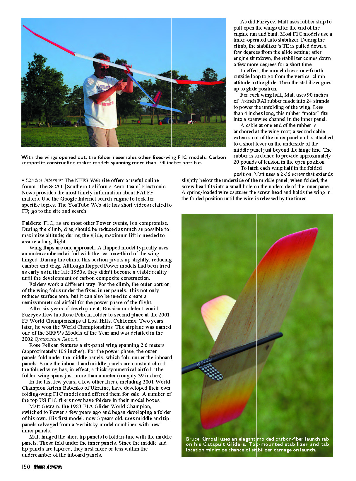
With the wings opened out, the folder resembles other fixed-wing F1C models. Carbon composite construction makes models spanning more than 100 inches possible.
Use the Internet: The NFFS Web site offers a useful online forum. The SCAT (Southern California Aero Team) Electronic News provides the most timely information about FAI FF matters. Use the Google Internet search engine to look for specific topics. The YouTube Web site has short videos related to FF; go to the site and search.
Folders:
F1C, as are most other Power events, is a compromise. During the climb, drag should be reduced as much as possible to maximize altitude; during the glide, maximum lift is needed to assure a long flight.
Wing flaps are one approach. A flapped model typically uses an undercambered airfoil with the rear one-third of the wing hinged. During the climb, this section pivots up slightly, reducing camber and drag. Although flapped Power models had been tried as early as in the late 1950s, they didn’t become a viable reality until the development of carbon composite construction.
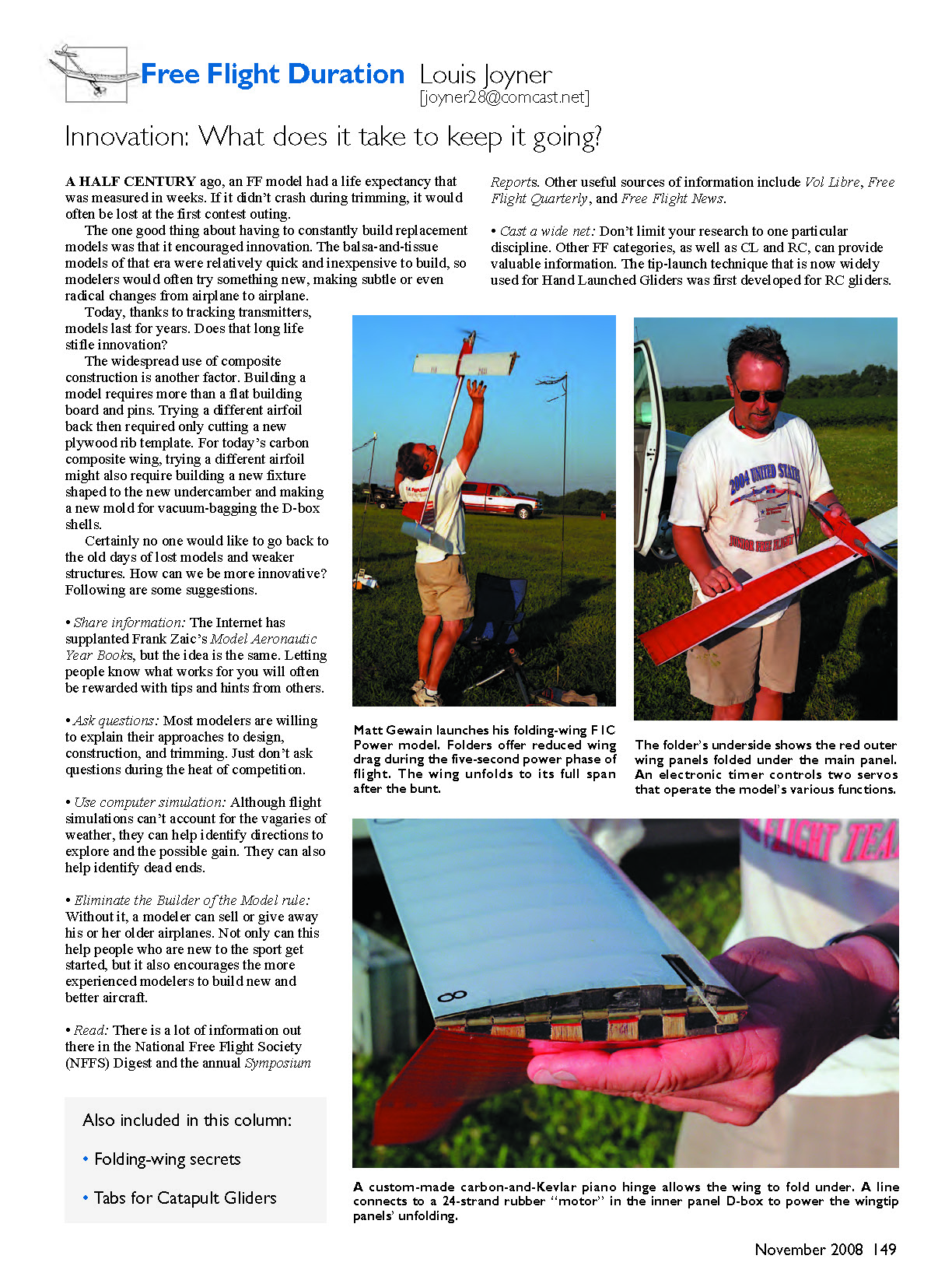
Folders work a different way. For the climb, the outer portion of the wing folds under the fixed inner panels. This not only reduces surface area, but it can also be used to create a semisymmetrical airfoil for the power phase of the flight.
After six years of development, Russian modeler Leonid Fuzeyev flew his Rose Pelican folder to second place at the 2001 FF World Championships at Lost Hills, California. Two years later, he won the World Championships. The airplane was named one of the NFFS’s Models of the Year and was detailed in the 2002 Symposium Report.
Rose Pelican features a six-panel wing spanning 2.6 meters (approximately 105 inches). For the power phase, the outer panels fold under the middle panels, which fold under the inboard panels. Since the inboard and middle panels are constant chord, the folded wing has, in effect, a thick symmetrical airfoil. The folded wing spans just more than a meter (roughly 39 inches).
In the last few years, a few other fliers, including 2001 World Champion Artem Babenko of Ukraine, have developed their own folding-wing F1C models and offered them for sale. A number of the top US F1C fliers now have folders in their model boxes.
Matt Geisain, the 1983 F1A Glider World Champion, switched to Power a few years ago and began developing a folder of his own. His first model, now 3 years old, uses middle and tip panels salvaged from a Verbitsky model combined with new inner panels.
Matt hinged the short tip panels to fold in-line with the middle panels. Those fold under the inner panels. Since the middle and tip panels are tapered, they nest more or less within the undercamber of the inboard panels.
As did Fuzeyev, Matt uses rubber strip to pull open the wings after the end of the engine run and bunt. Most F1C models use a timer-operated auto stabilizer. During the climb, the stabilizer’s TE is pulled down a few degrees from the glide setting; after engine shutdown, the stabilizer comes down a few more degrees for a short time.
In effect, the model does a one-fourth outside loop to go from the vertical climb attitude to the glide. Then the stabilizer goes up to glide position.
For each wing half, Matt uses 90 inches of 1/8-inch FAI rubber made into 24 strands to power the unfolding of the wing. Less than 4 inches long, this rubber “motor” fits into a spanwise channel in the inner panel.
A cable at one end of the rubber is anchored at the wing root; a second cable extends out of the inner panel and is attached to a short lever on the underside of the middle panel just beyond the hinge line. The rubber is stretched to provide approximately 20 pounds of tension in the open position.
To latch each wing half in the folded position, Matt uses a 2-56 screw that extends slightly below the underside of the middle panel; when folded, the screw head fits into a small hole on the underside of the inner panel. A spring-loaded wire captures the screw head and holds the wing in the folded position until the wire is released by the timer.
To control the model's various functions, Matt uses an electronic timer of his own design that is coupled to two servos. One servo operates the auto stabilizer and DT; the other servo controls motor run, wing unfold, and auto rudder.
Although the first model has never crashed, thanks to radio-controlled instant DT, Matt admits that it has gone through a number of changes.
"The first version was 150 grams overweight," he said. "It's been re-engineered four times trying to get the weight down."
The first test bed has led to two new models that have been built from scratch as folders. On these, the airfoil is a slightly thickened version of the Benedek B-7471 that is often used on F1A Gliders.
Instead of the six-panel wing, Matt has opted for a four-panel arrangement with equal panel lengths and tapered inner and outer panels. On the newest wing, he uses a narrower D-box that tapers from 1 1/8 inches at the root to only 3/8 inch at the tip.
The D-box is molded from two layers of 2.4-ounce carbon cloth set on the bias. Using two layers of cloth allows Matt to eliminate intermediate ribs within each D-box section.
Unlike conventional or flapped F1C models, the bending loads on a folding-wing model are much less. On a folder, the bunt loads occur with the wing in folded position. "You can make the wings much weaker, especially the tips," said Matt.
Catapult Glider Tabs:
If you don't count the Jim Walker Interceptors I flew as a boy, this year was my first try at Catapult Glider. It's probably the most fun for the least amount of effort of any FF event. The only problem I encountered was with the tab used to hold the model for launch.
On some designs, the fuselage extends an inch or so beyond the stabilizer to form a grip. Others have a tab below the fuselage somewhere between the wing TE and the stabilizer LE. The behind-the-stabilizer location adds extra weight where you don't want it and limits the amount of stretch for launch. But, as I was to find out, it's a bit easier on the stabilizer.
I used a tab location that was nearly halfway back along the tailboom. Unfortunately, that placement meant that the stabilizer LE occasionally hit my hand on launch.
After repairing the stabilizer a few times, I decided that I was gripping the tab too close to the tailboom. Installing a short, nylon 2-56 screw through the tab near the end did help keep my hand farther from the tailboom, but I was still causing occasional stabilizer damage.
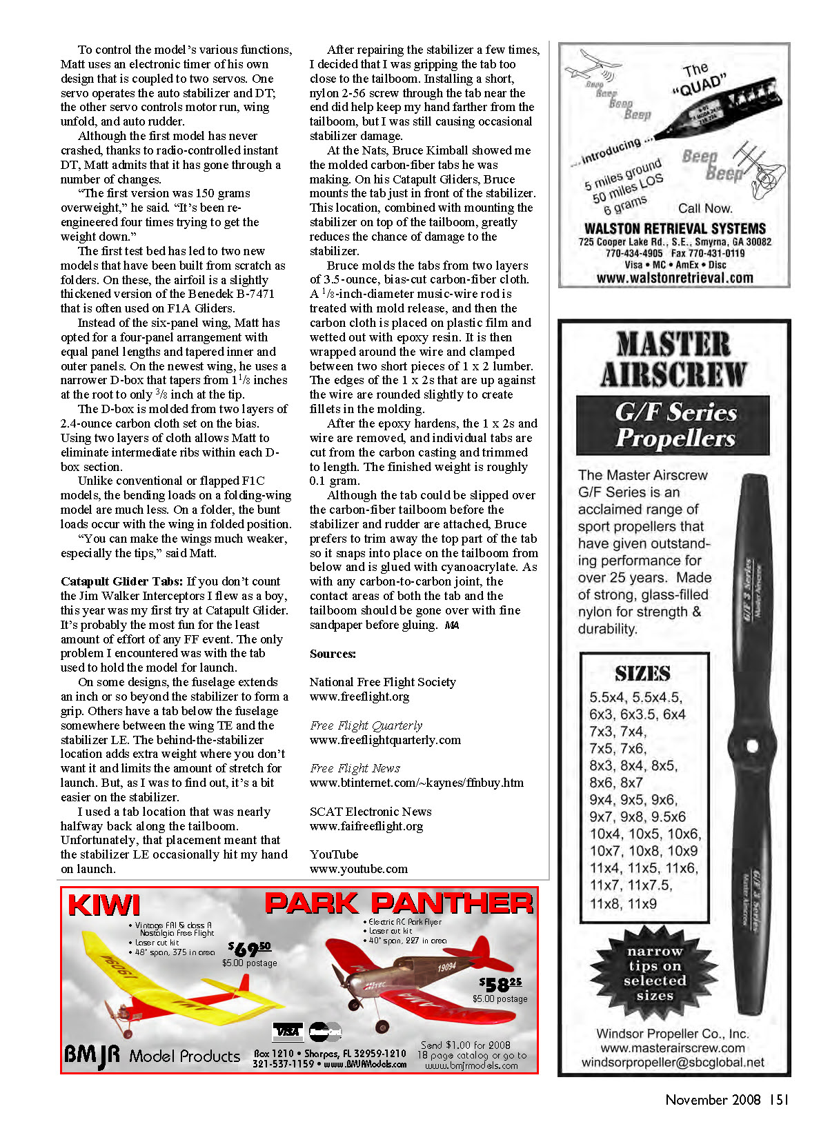
At the Nats, Bruce Kimball showed me the molded carbon-fiber tabs he was making. On his Catapult Gliders, Bruce mounts the tab just in front of the stabilizer. This location, combined with mounting the stabilizer on top of the tailboom, greatly reduces the chance of damage to the stabilizer.
Bruce molds the tabs from two layers of 3.5-ounce, bias-cut carbon-fiber cloth. A 1/8-inch-diameter music-wire rod is treated with mold release, and then the carbon cloth is placed on plastic film and wetted out with epoxy resin. It is then wrapped around the wire and clamped between two short pieces of 1 x 2 lumber. The edges of the 1 x 2s that are up against the wire are rounded slightly to create fillets in the molding.
After the epoxy hardens, the 1 x 2s and wire are removed, and individual tabs are cut from the carbon casting and trimmed to length. The finished weight is roughly 0.1 gram.
Although the tab could be slipped over the carbon-fiber tailboom before the stabilizer and rudder are attached, Bruce prefers to trim away the top part of the tab so it snaps into place on the tailboom from below and is glued with cyanoacrylate. As with any carbon-to-carbon joint, the contact areas of both the tab and the tailboom should be gone over with fine sandpaper before gluing. MJA
Sources:
National Free Flight Society www.freeflight.org
Free Flight Quarterly www.freeflightquarterly.com
Free Flight News www.btinternet.com/~kaynes/ffnbuy.htm
SCAT Electronic News www.faifreeflight.org
YouTube www.youtube.com
Transcribed from original scans by AI. Minor OCR errors may remain.

