
FREE FLIGHT INDOOR
Bud Tenny, Box 830545, Richardson TX 75083
IN 2002 Science Olympiad (SO) will again be working with kids in high schools across the country. My best information at this time is that the Wright Stuff activity will be held again.
Most of the SO activity has very capable mentors, but entrants in the Wright Stuff event really need the guidance of experienced model-airplane fliers. I believe you can contact high schools in your area to learn if Science Olympiad is active there.
If it's not or you are unsure of how to proceed, Vern Hacker (in the Cleveland OH area) may be able to help you find Wright Stuff entrants who need mentors.
The following E-mail message from Hack (<REDACTED>) gives the particulars.
"I am most pleased to be a source of referrals for the SO people. That is the reason I have acquired the lists. If you have lost the phone number, it is <REDACTED>."
Read This (from Dave Linstrum): Jesse Aronstein's "The Model Club and the Science Olympiad" was published in the 2001 Symposium report.
This paper describes, in detail, the experience Jesse and his Mid-Hudson Modelmasters clubmates had in the past three years at the school level, where the need for mentoring is greatest. It is required reading for any Indoor flier who wants to mentor kids effectively.
The 2001 National Free Flight Society (NFFS) Symposium report (155 pages) is available for $25 + $4 postage paid to NFFS members ($30 + $4 for nonmembers). It is sent by Priority Mail in the US.
Send a check or money order to NFFS, Bob McLinden, Box 7967, Baltimore MD 21201.
The flight times from the Indoor Team Finals, held at the Akron OH site, will surely have been published numerous places before this column is published in Model Aviation. Steve Brown was kind enough to share these observations.
"In case you haven't heard, the Team Finals results are:
"1. Richmond "2. Cailliau "3. Brown
"Richmond flew a 65 cm fuselage with a 16-inch stick (the model from the 2000 salt mine) with an unbraced wing. The motor was centered on the stick between two wire spacers and driven by his 22 x 18 variable diameter prop.
"Amazingly, he managed to get this thing to climb to about 110 feet altitude.
"For the Juniors: "1. Doug Schaefer "2. Parker Parrish "3. Ben Saks"
Pretty good VP prop. He had times of 29:42 and 27:55, which is better than the last one—half of the seniors. Doug is a bright kid who has been flying F1D about six months.
“The big issue for these models is the 0.6-gram rubber weight limit. We’re going to have to find ways to make them fly on smaller cross-section rubber or at a lower prop rpm. There is just no way to get more turns into the ‘standard’ nine-inch loop of 0.050-inch width.”
Custom Propeller Fixtures: The previous column showed a custom “block” that is constructed from precisely calculated station blocks that allow any desired pitch angle at any station.
This versatility comes with the requirement that each custom station block has to be calculated, constructed, then precisely aligned at the propeller spar location.
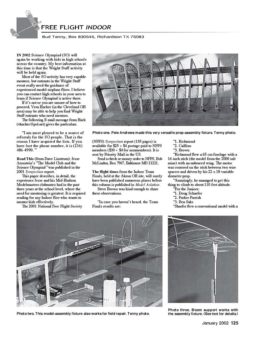
Many years ago, the late Pete Andrews constructed a universal propeller fixture that very neatly sidesteps all the nagging problems inherent in my “versatile” propeller construction block.
Photo one shows the fixture Pete built. The major critical problem—station alignment—is solved by the pivot rod that mounts each station block. No matter what angle each station is set to, alignment is automatically correct.
The same is true for spacing between the station(s). For a really long propeller blade, the stations can be set farther apart. For a smaller-diameter propeller, the stations can be moved closer to retain the same pitch angles at each propeller station.
Since the actual pitch is defined by the blade angle and the diameter of the circle traced by the particular blade element, moving the blade stations changes the pitch of that blade element.
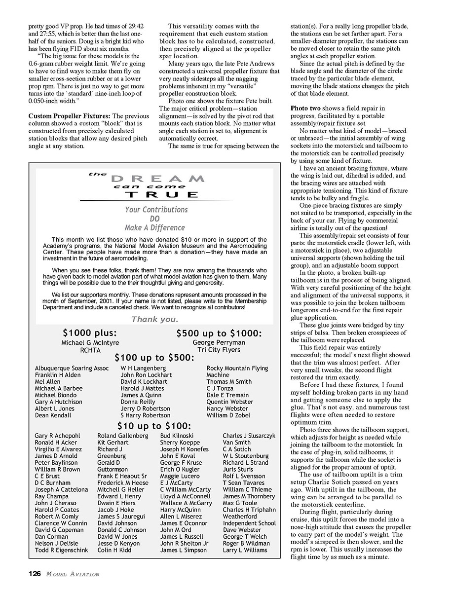
Photo two shows a field repair in progress, facilitated by a portable assembly/repair fixture set.
No matter what kind of model—braced or unbraced—the initial assembly of wing sockets into the motorstick and tailboom to the motorstick can be controlled precisely by using some kind of fixture.
I have an ancient bracing fixture, where the wing is laid out, dihedral is added, and the bracing wires are attached with appropriate tensioning. This kind of fixture tends to be bulky and fragile.
One-piece bracing fixtures are simply not suited to be transported, especially in the back of your car. Flying by commercial airline is totally out of the question!
This assembly/repair set consists of four parts: the motorstick cradle (lower left, with a motorstick in place), two adjustable universal supports (shown holding the tail group), and an adjustable boom support.
In the photo, a broken built-up tailboom is in the process of being aligned. With very careful positioning of the height and alignment of the universal supports, it was possible to join the broken tailboom longerons end-to-end for the first repair glue application.
These glue joints were bridged by tiny strips of balsa. Then broken crosspieces of the tailboom were replaced.
This field repair was entirely successful; the model’s next flight showed that the trim was almost perfect. After very small tweaks, the second flight restored the trim exactly.
Before I had these fixtures, I found myself holding broken parts in my hand and getting someone else to apply the glue. That’s not easy, and numerous test flights were often needed to restore optimum trim.
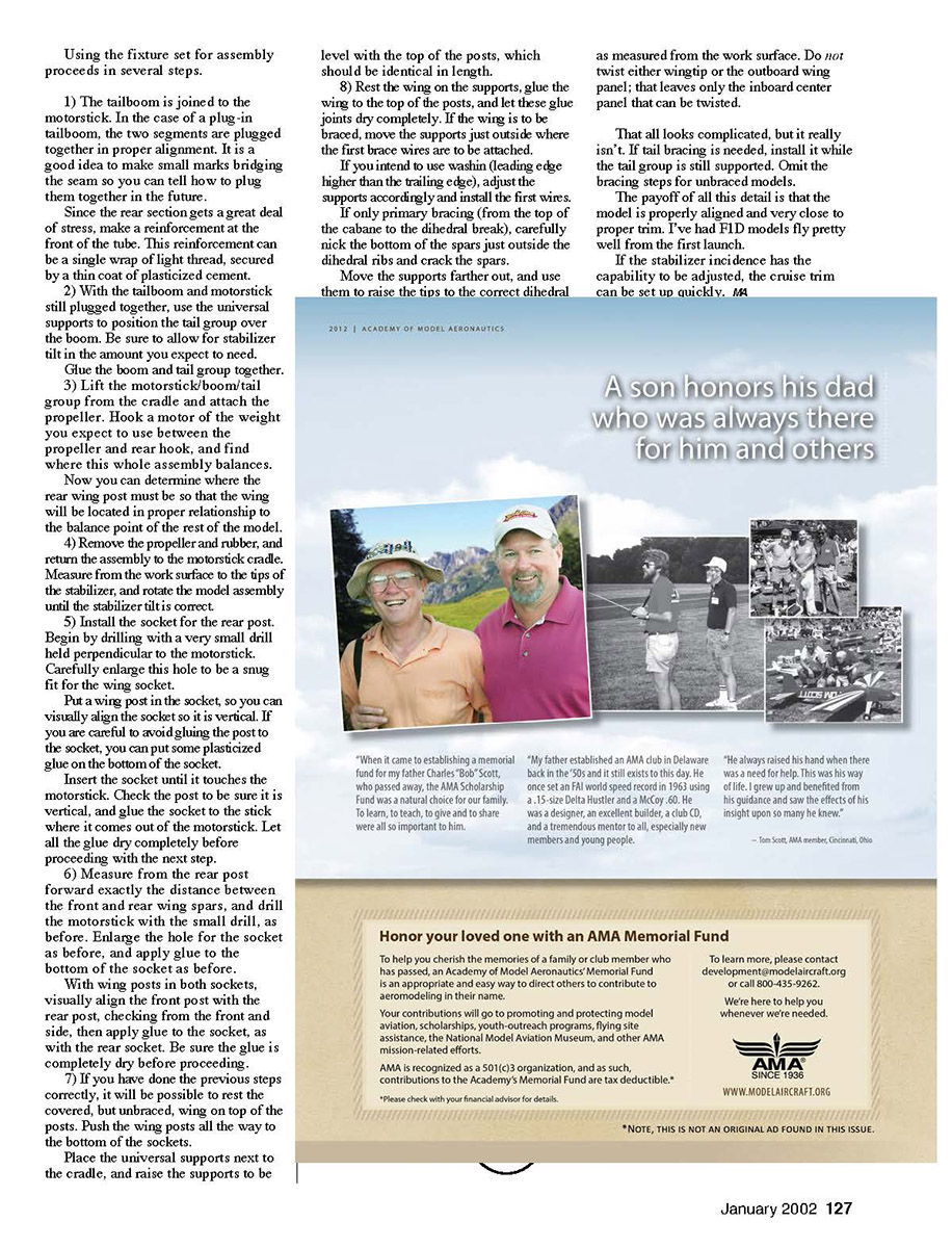
Photo three shows the tailboom support, which adjusts for height as needed while joining the tailboom to the motorstick. In the case of plug-in, solid tailbooms, it supports the tailboom while the socket is aligned for the proper amount of upthrust.
The use of tailboom uptilt is a trim setup Charlie Sotich passed on years ago. With uptilt in the tailboom, the wing can be arranged to be parallel to the motorstick centerline.
During flight, particularly during a cruise, this uptilt forces the model into a nose-high attitude that causes the propeller to carry part of the model’s weight. The model’s airspeed is then slower, and the rpm is lower. This usually increases the flight time by as much as a minute.
FF Indoor
Using the fixture set for assembly proceeds in several steps.
- The tailboom is joined to the motorstick. In the case of a plug-in tailboom, the two segments are plugged together in proper alignment. It is a good idea to make small marks bridging the seam so you can tell how to plug them together in the future.
Since the rear section gets a great deal of stress, make a reinforcement at the front of the tube. This reinforcement can be a single wrap of light thread, secured by a thin coat of plasticized cement.
- With the tailboom and motorstick still plugged together, use the universal supports to position the tail group over the boom. Be sure to allow for stabilizer tilt in the amount you expect to need.
Glue the boom and tail group together.
- Lift the motorstick/boom/tail group from the cradle and attach the propeller. Hook a motor of the weight you expect to use between the propeller and rear hook, and find where this whole assembly balances.
Now you can determine where the rear wing post must be so that the wing will be located in proper relationship to the balance point of the rest of the model.
- Remove the propeller and rubber, and return the assembly to the motorstick cradle. Measure from the work surface to the tips of the stabilizer, and rotate the model assembly until the stabilizer tilt is correct.
- Install the socket for the rear post. Begin by drilling with a very small drill held perpendicular to the motorstick. Carefully enlarge this hole to be a snug fit for the wing socket.
Put a wing post in the socket, so you can visually align the socket so it is vertical. If you are careful to avoid gluing the post to the socket, you can put some plasticized glue on the bottom of the socket.
Insert the socket until it touches the motorstick. Check the post to be sure it is vertical, and glue the socket to the stick where it comes out of the motorstick. Let all the glue dry completely before proceeding with the next step.
- Measure from the rear post forward exactly the distance between the front and rear wing spars, and drill the motorstick with the small drill, as before. Enlarge the hole for the socket as before, and apply glue to the bottom of the socket as before.
With wing posts in both sockets, visually align the front post with the rear post, checking from the front and side, then apply glue to the socket, as with the rear socket. Be sure the glue is completely dry before proceeding.
- If you have done the previous steps correctly, it will be possible to rest the covered, but unbraced, wing on top of the posts. Push the wing posts all the way to the bottom of the sockets.
Place the universal supports next to the cradle, and raise the supports to be level with the top of the posts, which should be identical in length.
- Rest the wing on the supports, glue the wing to the top of the posts, and let these glue joints dry completely. If the wing is to be braced, move the supports just outside where the first brace wires are to be attached.
If you intend to use washin (leading edge higher than the trailing edge), adjust the supports accordingly and install the first wires.
If only primary bracing (from the top of the cabane to the dihedral break), carefully nick the bottom of the spars just outside the dihedral ribs and crack the spars.
Move the supports farther out, and use them to raise the tips to the correct dihedral as measured from the work surface. Do not twist either wingtip or the outboard wing panel; that leaves only the inboard center panel that can be twisted.
That all looks complicated, but it really isn’t. If tail bracing is needed, install it while the tail group is still supported. Omit the bracing steps for unbraced models.
The payoff of all this detail is that the model is properly aligned and very close to proper trim. I’ve had F1D models fly pretty well from the first launch.
If the stabilizer incidence has the capability to be adjusted, the cruise trim can be set up quickly.
Transcribed from original scans by AI. Minor OCR errors may remain.

