
FREE FLIGHT SPORT and SCALE
Fernando Ramos 19361 Mesa Dr., Villa Park, CA 92861 E-mail: [email protected]
Electric power: reluctance and observations
The old adage "You can't teach an old dog new tricks" certainly applies to me. I have tried electric power on several fronts, and each time I have been thwarted for one reason or another. It seems as though I have this aura around electrons that causes things to go bonkers.
I have seen beautiful Free Flight (FF) Scale models—particularly multiengine—powered by electric that fly realistically. I see the advantage of not having to wipe off the model after each flight, just turning on a switch to get them to go, etc.
However, I get weak in the knees when I have to pick up a battery pack and place it in a model. The batteries often weigh more than the entire aircraft! I also admit that I don't particularly like the sound of the fan up front; give me a diesel or an ignition engine for that lovely noise and smell.
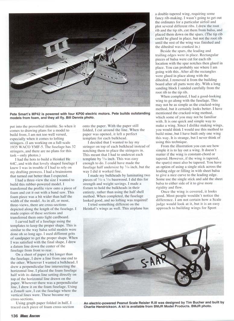
One of my Wednesday flying buddies is flying an all-foam model (span approximately 16 inches) powered with a very small nickel‑metal hydride battery. He is consistently getting two-minute flights with it. I can see where a dime-scale model would be fun to fly with the small motor and battery. The simplicity of the setup appeals to me: a little motor, a little battery, a little propeller, and a little airplane—something you can almost fly in your backyard.
That doesn't mean I can't be persuaded to add electric to my FF stable. I really haven't had the motivation. I still prefer CO2 over electric; it does sound like a real airplane! Maybe someday, but not now.
As I sit here thinking about electric, I finally figured out why I have no interest. I get several model magazines each month, and I do mean several. In the sections that deal with electric (mostly Radio Control), it seems as though there are a zillion new motors each month, each with its own characteristics. Trying to cope with the battery requirements, voltage, and charging rates—forget it.
I just put fuel in the tank, flip the propeller, and I'm off for another flight. I call that simple, and at my age simple is what I like. I have enough clutter in my brain, and I don't need any more!
One of my objectives in writing this column is to pass along hints that make your modeling easier and still create the illusion of a full‑scale airplane.
Drafting and building without lofting
In all the years I spent in school, I had only one semester in drafting—in junior high. What I know about drafting could be put into the proverbial thimble. So when it comes to drawing plans for a model to build from, I am not too well versed, especially when it comes to lofting stringers. (I am working on a full‑scale 1935 WACO YMF‑5. The fuselage has 32 stringers, and there are no plans for this task—only photos.)
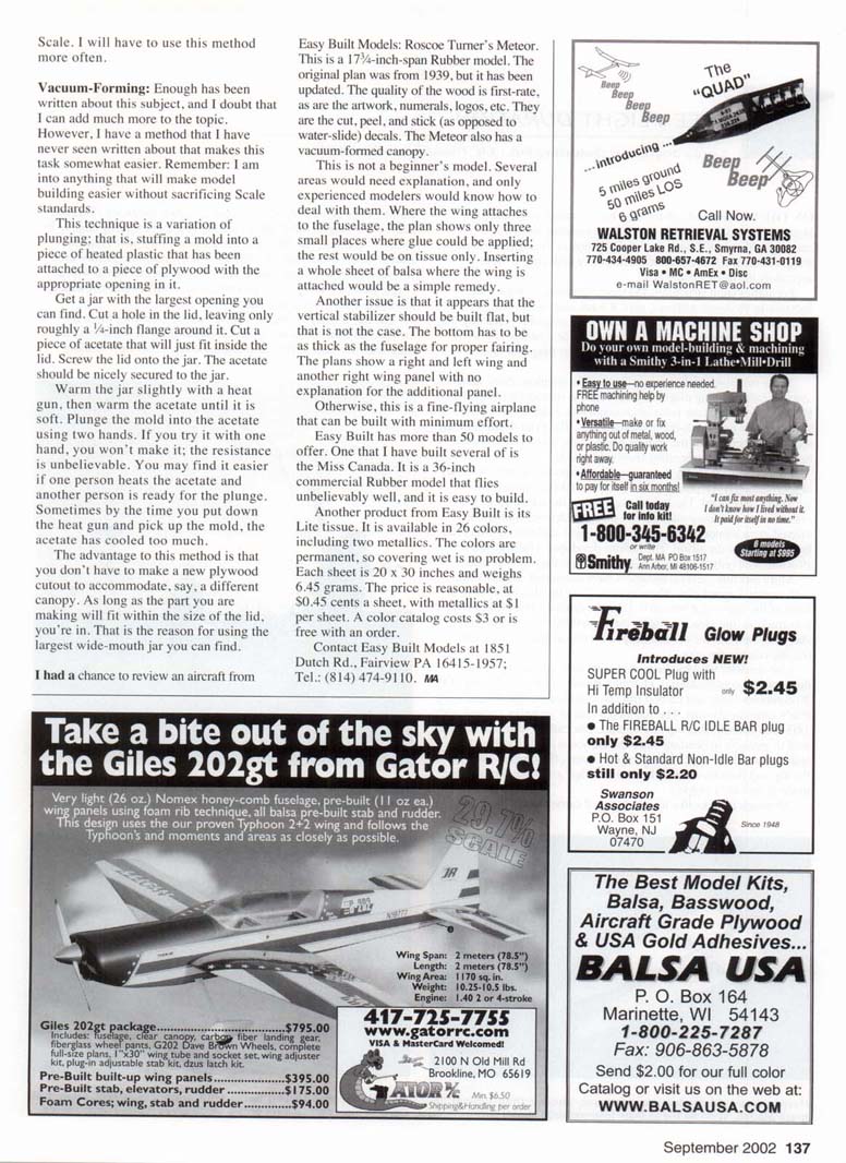
I wanted to build a Heinkel He 64C, and with that lovely shaped fuselage I knew I was in trouble if I had to rely on my drafting prowess. I had a brainstorm that turned out better than I expected: I used a three‑view the size I wanted the rubber‑powered model to be and transferred the profile view onto a piece of foam, which I cut out with a band saw. This foam piece was a bit wider than half the width of the model.
As in most three‑views, there are cross‑sections depicted along the fuselage. I copied those sections and transferred them onto light cardboard. I carved half of a fuselage using the templates to keep the proper shape—similar to the way solid balsa models were made years ago. I used different grits of sandpaper to get the proper shape. When satisfied with the final shape, I drew a datum line down the center of the fuselage from front to rear.
On a sheet of paper a bit longer than the fuselage, I drew a horizontal line from one end to the other. Wherever I wanted a bulkhead, I drew a perpendicular line intersecting the horizontal line. I placed the foam fuselage half with its datum line directly on top of the horizontal line drawn on the paper. Wherever there was a perpendicular line, I transferred it to the foam fuselage and cut the fuselage at those vertical lines using a Zona saw. These cut pieces became my cross‑sections.
I then traced each foam cross‑section onto graph paper folded in half. With the paper still folded, I cut around the line and, when opened, had a perfect template for each bulkhead.
I decided to lay my stringers on top of each bulkhead instead of notching the bulkheads to place the stringers in. This meant that I had to undercut each template by 1/16 inch, which was easy to do. I could have made the fuselage half undersize by 1/16 inch, but the way I did it worked fine.
I made my bulkheads by laminating two pieces of 1/32 x 1 1/16 inch basswood for strength and weight savings. I made a fixture to hold the bulkheads in their entirety, rather than using the half‑shell method. When completed, the fuselage looked good, and no lofting was required!
Wing construction method
I tried something different on the Heinkel's wings as well. This airplane has a double‑tapered wing, requiring some fancy rib‑making. I wasn't going to get out the ordinates for a particular airfoil and plot several different ribs. Instead, I drew the root rib and the tip rib, cut them from balsa, and placed them down on the spars. (The tip rib could be glued in place, but not the root rib until the rest of the wing was finished and the dihedral was set.)
With the spars in place, and the leading and trailing edges installed, I cut rectangular pieces of balsa for each rib location with the spar notches, then glued them in place. After all the rectangles were glued in and the dihedral set, I removed the wing from the building board once everything was dry. Using a long sanding block, I sanded carefully from the root rib to the tip rib.
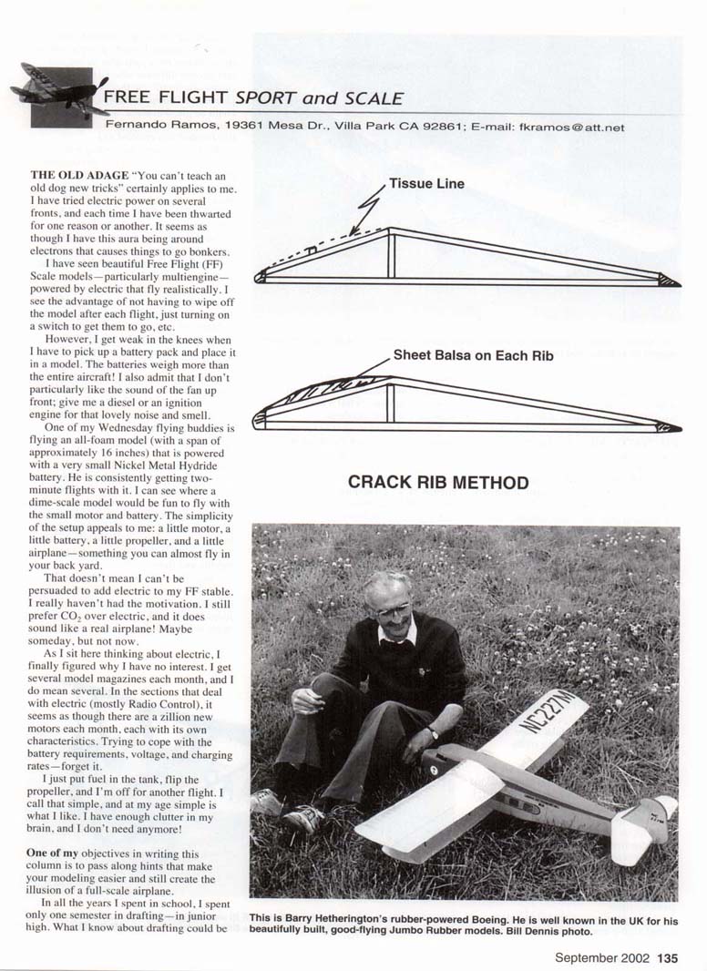
When completed, I had a good‑looking wing to go along with the fuselage. This may not be as simple as the cracked‑wing method, but it certainly looks better. I have mentioned the cracked‑wing method before; it is one quick and simple way to make a wing. Since I dislike making wings, you would think I would use that method more often, but I have built only one wing that way.
From the illustration you can see how simple it is to lay out a wing. It doesn't matter if the wing is constant‑chord or tapered; however, if the wing is tapered, the spar(s) must also be tapered. You have the option of using a single stick across the leading edge or filling in with sheet balsa to give a nice curve to the leading edge. Some use a single stick and add sheet balsa to either side of it to give more rigidity and flow.
Once the wing is covered, it looks good. Most people wouldn't notice the difference. I am not certain how a Scale judge would view it, but it is an easy approach to building wings for Sport and Scale models. I will have to use this method more often.
Vacuum‑forming: a simple plunge variation
Enough has been written about vacuum‑forming, and I doubt I can add much to the topic. However, I have a method I have never seen written about that makes the task somewhat easier. Remember: I am into anything that will make model building easier without sacrificing Scale standards.
This technique is a variation of plunging—stuffing a mold into a piece of heated plastic that has been attached to a piece of plywood with the appropriate opening in it.
Steps:
- Get a jar with the largest opening you can find.
- Cut a hole in the lid, leaving only roughly a 1/4‑inch flange around it.
- Cut a piece of acetate that will just fit inside the lid.
- Screw the lid onto the jar so the acetate is secured in the lid.
- Warm the jar slightly with a heat gun, then warm the acetate until it is soft.
- Plunge the mold into the acetate using two hands. (One person to heat the acetate and another ready to plunge can make this easier; the resistance is surprising and the acetate cools quickly.)
The advantage of this method is that you don't have to make a new plywood cutout to accommodate, say, a different canopy. As long as the part you are making will fit within the size of the lid, you're in. That is the reason for using the largest wide‑mouth jar you can find.
Review: Easy Built Models — Roscoe Turner's Meteor
I had a chance to review an aircraft from Easy Built Models: Roscoe Turner's Meteor. This is a 17‑1/4‑inch‑span rubber model. The original plan was from 1939, but it has been updated. The quality of the wood is first‑rate, as are the artwork, numerals, logos, etc. The decals are cut, peel‑and‑stick (as opposed to water‑slide). The Meteor also has a vacuum‑formed canopy.
This is not a beginner's model. Several areas would need explanation, and only experienced modelers would know how to deal with them. For example, where the wing attaches to the fuselage the plan shows only three small places where glue could be applied; the rest would be on tissue only. Inserting a whole sheet of balsa where the wing is attached would be a simple remedy.
Another issue is that the vertical stabilizer should not be built flat—the bottom has to be as thick as the fuselage for proper fairing. The plans show a right and left wing and another right wing panel with no explanation for the additional panel.
Otherwise, this is a fine‑flying airplane that can be built with minimum effort.
Other Easy Built Models and products
Easy Built has more than 50 models to offer. One that I have built several times is the Miss Canada. It is a 36‑inch commercial rubber model that flies unbelievably well and is easy to build.
Easy Built also offers Lite tissue available in 26 colors, including two metallics. The colors are permanent, so covering wet is no problem. Each sheet is 20 x 30 inches and weighs 6.45 grams. Price: $0.45 a sheet, metallics $1 per sheet. A color catalog costs $3 or is free with an order.
Contact Easy Built Models: 1851 Dutch Rd., Fairview, PA 16415‑1957 Tel.: (814) 474‑9110
MA
Transcribed from original scans by AI. Minor OCR errors may remain.

