
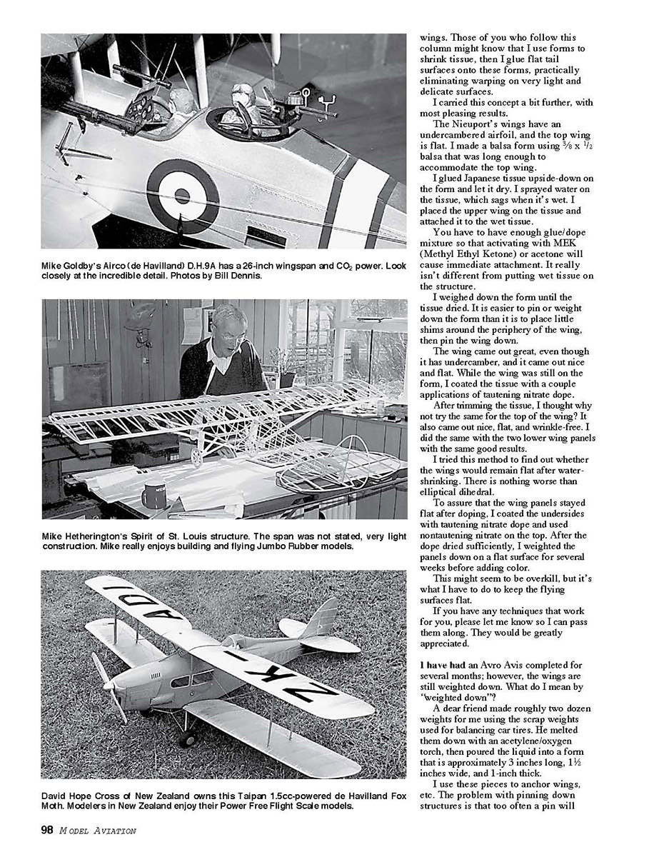
FREE FLIGHT SPORT and SCALE
Fernando Ramos, 19361 Mesa Dr., Villa Park CA 92861; E-mail: [email protected]
MY MOTHER used an old expression when it was appropriate: “Each one to his own taste said the woman as she kissed the cow.” Nothing could be more true when it comes to modeling.
Consider the variety of models one can choose from any of the many categories in Free Flight (FF), Radio Control (RC), and Control Line (CL).
Some modelers like to build and fly in each of the aforementioned categories, and more power to them. It takes someone special to be good at flying the various disciplines, not to mention the time involved.
FF is my number-one interest, with Scale at the top. I feel fortunate to have found this sport many years ago.
FF Scale has to be one of the toughest events, whether it’s with rubber or electric power, internal combustion, or CO2.
You must check to see that you have all the flying surfaces warp-free, that the center of gravity is right on, and that the thrustline is where it belongs. If you don’t have the tall proverbial grass to test over, your model may not survive the first flight!
The thrill of watching an FF Scale model fly overhead is rewarding and challenging. One of the reasons I do this column is to hopefully I can spur someone to take up the challenge.
There are so many model designs that barely look like airplanes (which have no appeal to me), thus my mom’s expression. I can’t imagine spending any amount of time on a model that doesn’t look like an airplane.
Even Old-Timers, which I love next to Scale, have to have a cabin and landing gear.
It’s time to get out that Scale model you’ve always wanted to build; we all need a challenge! Hopefully some of the following hints will make your job easier.
In several columns I have pointed out many areas where you are likely to find mistakes in the plans from which you are building. A few more have crossed my path.
I mentioned that I have started my model for next year’s Flying Aces Club Nationals. The plans are exquisite to look at (I wish I could draw like that). Even though the plans are extraordinary, use caution.
I had the fuselage framed and was ready to add bulkheads. (These plans show the usual side view, top view, and a cross-section at each station showing the shape of the bulkheads.)
I used the top view to frame the fuselage. When I cut the first bulkheads, they weren’t as wide as depicted on the top view. That was no big deal, except that I had to redraw each one, making certain it would fit the fuselage correctly.
As I mentioned before, one of my favorite World War I airplanes is the Nieuport 11. I am almost finished with a spiffy little model of one for my .008-cubic-inch diesel.
The rear cabane struts are vertical and attach to the rear spar. The front ones are inverted “V”s and attach to the front spar. The plans show where the holes should be drilled in the spars.
I had the presence of mind to measure the distance between the rear cabanes, but the dimension did not concur with the plans.
On a glance I didn’t drill where the plans showed, since holes in spars (vertical ones) are not desirable. I did reinforce the area with carbon fiber where the holes were drilled.
Since the Nieuport has a flat wing and trimming could become a problem, I made the ailerons movable. No problem, except that the width of the “V” interplane struts intersected where the aileron leading edge was, so I had to change the width of the struts.
There seems to be no end to the areas where errors can be made!
I tried something a bit different when it came time to cover the Nieuport’s wings. No pins were used to hold the ribs down when the dihedral was set. Instead, a small strip of glassine was placed under each rib and then the wing was hinged. When the dihedral was correct, the ribs were stuck down with Solvaset and a couple minutes later the glassine peeled right off leaving no scars. Works like a charm.
One of the biggest headaches I have encountered is in getting that “scale” look in open-cockpit models. A realistic pilot can do much to enhance the appearance. Don’t be afraid to spend a little time on this area; after all, it is the cockpit that people tend to look at when models are on display.
Speaking of display, the choice of finishing materials can make or break a model’s appearance. Do not use cheap dope or paints that will wrinkle or shrink excessively. I have seen many beautiful models ruined by poor finishing choices.
Finally, don’t be afraid to ask other modelers for help. The FF community is full of people willing to share their experience and knowledge. If you’re persistent, patient, and willing to learn, your next Scale model might be the best one yet.
Those of you who follow this column might know that I use forms to shrink tissue, then I glue flat tail surfaces onto these forms, practically eliminating warping on very light and delicate surfaces.
I carried this concept a bit further, with most pleasing results.
The Nieuport’s wings have an undercambered airfoil, and the top wing is flat. I made a balsa form using 3/8 x 1/2 balsa that was long enough to accommodate the top wing.
I glued Japanese tissue upside-down on the form and let it dry. I sprayed water on the tissue, which sags when it’s wet. I placed the upper wing on the tissue and attached it to the wet tissue.
You have to have enough glue/dope mixture so that activating with MEK (Methyl Ethyl Ketone) or acetone will cause immediate attachment. It really isn’t different from putting wet tissue on the structure.
I weighed down the form until the tissue dried. It is easier to pin or weight down the form than it is to place little shims around the periphery of the wing, then pin the wing down.
The wing came out great, even though it has undercamber, and it came out nice and flat. While the wing was still on the form, I coated the tissue with a couple applications of tautening nitrate dope.
After trimming the tissue, I thought why not try the same for the top of the wing? It also came out nice, flat, and wrinkle-free. I did the same with the two lower wing panels with the same good results.
I tried this method to find out whether the wings would remain flat after water-shrinking. There is nothing worse than elliptical dihedral.
To assure that the wing panels stayed flat after doping, I coated the undersides with tautening nitrate dope and used a nontautening nitrate on the top. After the dope dried sufficiently, I weighted the panels down on a flat surface for several weeks before adding color.
This might seem to be overkill, but it’s what I have to do to keep the flying surfaces flat.
If you have any techniques that work for you, please let me know so I can pass them along. They would be greatly appreciated.
I have had an Avro Avis completed for several months; however, the wings are still weighted down. What do I mean by “weighted down”?
A dear friend made roughly two dozen weights for me using the scrap weights used for balancing car tires. He melted them down with an acetylene/oxygen torch, then poured the liquid into a form that is approximately 3 inches long, 1½ inches wide, and 1-inch thick.
I use these pieces to anchor wings, etc. The problem with pinning down structures is that too often a pin will not penetrate into the bench and so the pin point works the wood and a hole is left. If a pin is left in place while weighting, the hole gets larger. The weights allow anchoring without causing damage.
The weights are heavy enough to hold very large panels flat. They are easy to make and cheap. If anyone would like a pattern or more information, send a stamped, self-addressed envelope to me and I’ll gladly send details.
Good luck with your Scale projects and happy building.
It used to frustrate me when I used dress snaps to attach a cowl to the fuselage. Several things would happen: one of the snaps would come loose, the snaps would misalign, or, no matter how hard I pushed, the snaps wouldn't snap.
I finally figured out a way to make this task easy. I will use the nose cowl attaching to the firewall as an example. This will be for a gas model since plywood has to be used.
At the same time I cut the firewall and what will be the back of the nose cowl from 1/16 plywood so both are identical. After gluing the firewall onto the fuselage, I decide whether I will use three or four snaps; three usually does the job.
I cyanoacrylate-glue (CyA) the male snaps in place. When the CyA has dried, I drill some small holes through the plywood behind the snap so I can sew them with a needle and thread. This will assure that they will not pull out after fuel gets on them.
The next step is the key to making snaps work the way they are intended. I align the plywood that is the back of the nose cowl with the firewall. I push gently against the male snaps to make an impression on the plywood. Then I drill three holes that are roughly 1/16-inch larger than the snaps.
I place some waxed paper over the male snaps, then I snap on the female part so the waxed paper is sandwiched between the parts.
I carefully align the nose cowl over the firewall and tape it in place, making certain that the two plywood parts are flush with each other. The female part of the snap protrudes a bit into the plywood, with a 1/16-inch gap around the hole.
I mix J-B Weld and carefully lay it around each female snap, encapsulating it. Take care that none of the mixture gets into the little spring; you may never get it off.
(J-B Weld should be in every household—not just for modeling but for myriad repair tasks around the house. You can find it in any hardware store. It can actually be machined after it has hardened!)
When the J-B Weld dries, I remove the nose-cowl plywood and check out how neat the snaps work and how flush the parts remain. The waxed paper is used to keep the J-B Weld from attaching itself where I don't want it.
Another tip for cowl attachment, or even wing attachment, is to use very small rare earth magnets. I think the first time I saw this clever idea was on Jack Moses' Jumbo Rubber model, for holding the wings onto the fuselage.
The advantage is that there are no unsightly rubber bands holding the wings on, and in a hard landing the wings pop off much easier than if they were held on with rubber bands. This, of course, means less damage.
These rare earth magnets are roughly 1/8 inch in diameter (you can buy larger ones) and are very powerful.
To digress, the physics teacher where I taught used to come into my classroom at the end of the year to proselyte students for the coming year. He always had neat demonstrations.
He came in with a three-foot piece of copper tubing, the size used for plumbing, and asked the students what would happen if he dropped the rare earth magnet into the copper tube.
Some students were sharp enough to realize that copper has no magnetic properties, and the magnet would simply fall through the tube. To the students' amazement, it took a bit of time for the magnet to get to the other end because of the formation of eddy currents.
The magnet the teacher used for the demonstration was roughly the size of a dime. One of these magnets is able to pick up a $10 bill, attracting any ferrous particles in the ink! These little suckers are powerful.
When using the magnets for holding down wings or cowls, you need some kind of alignment pins. When you get the wing or cowl near the opposite magnet, they snap into place.
The only condition is that you have to make certain you have the opposite pole on the opposing side.
You have one magnet glued in place, and you check the opposing one to see that you have the correct side properly aligned. Set the magnet down, add the glue, and pick up the magnet, attaching it on the opposite side.
I know of two places where you can buy rare earth magnets. One is from Dave Rees of HiLine, Box 11558, Goldsboro NC. They cost a buck a pair. If you order from Dave, make sure you include postage. The other place is RadioShack.
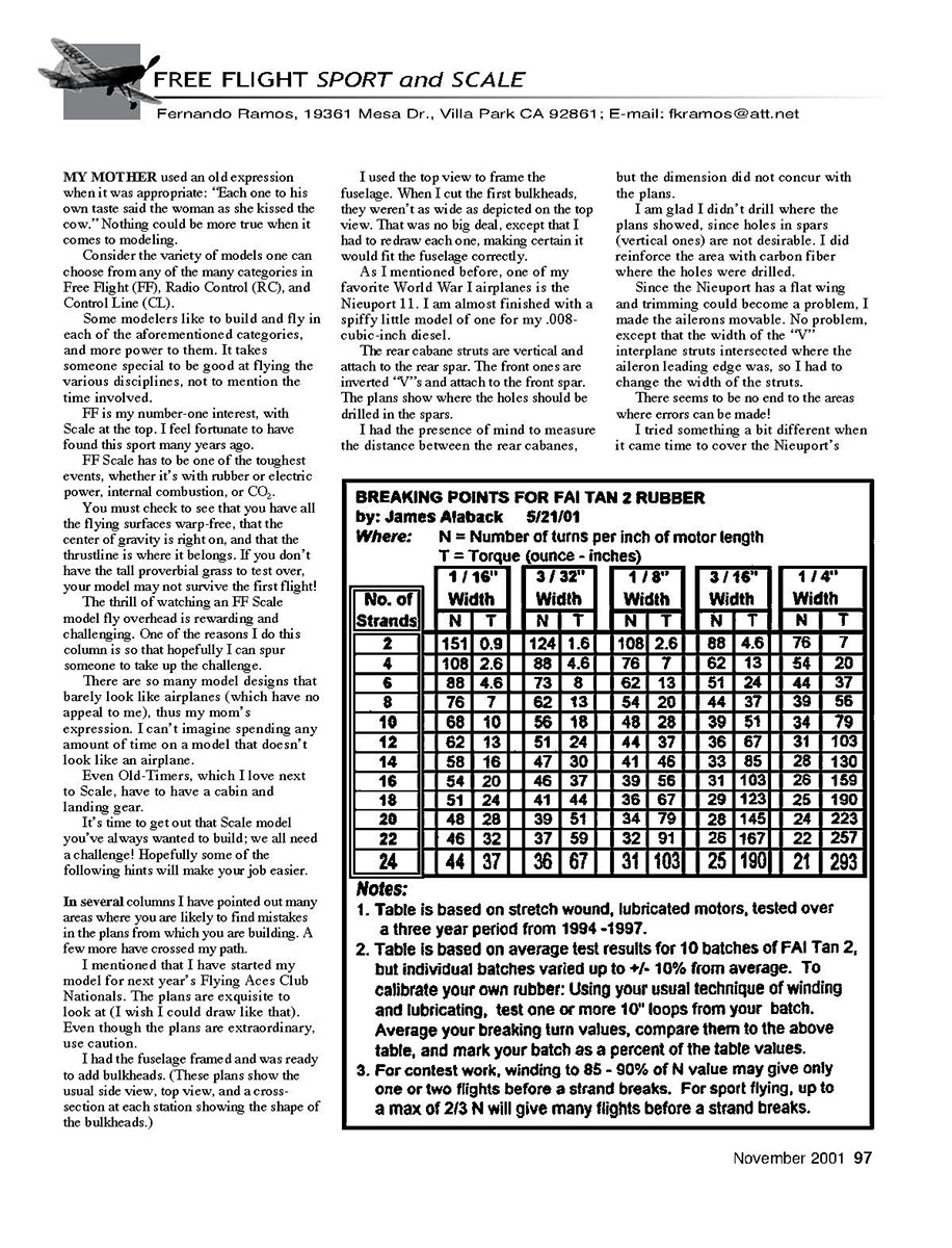
The chart included with this column was gleaned from the San Diego Scale Staff newsletter, edited by George Mansfield. It is a wonderful compilation by Jim Aback that gives the breaking points for FAI Tan II rubber.
Jim wrote for Flying Models for many years and has recently retired from that task. He is a consummate model builder, aero historian, competitor, and all-around great guy.
It took roughly three years—from 1994 to 1997—to gather this information; it wasn't done in one shot. MA
Transcribed from original scans by AI. Minor OCR errors may remain.

