
Finding Your Personal IMAC Setup - 2010/06
by Baron Johnson
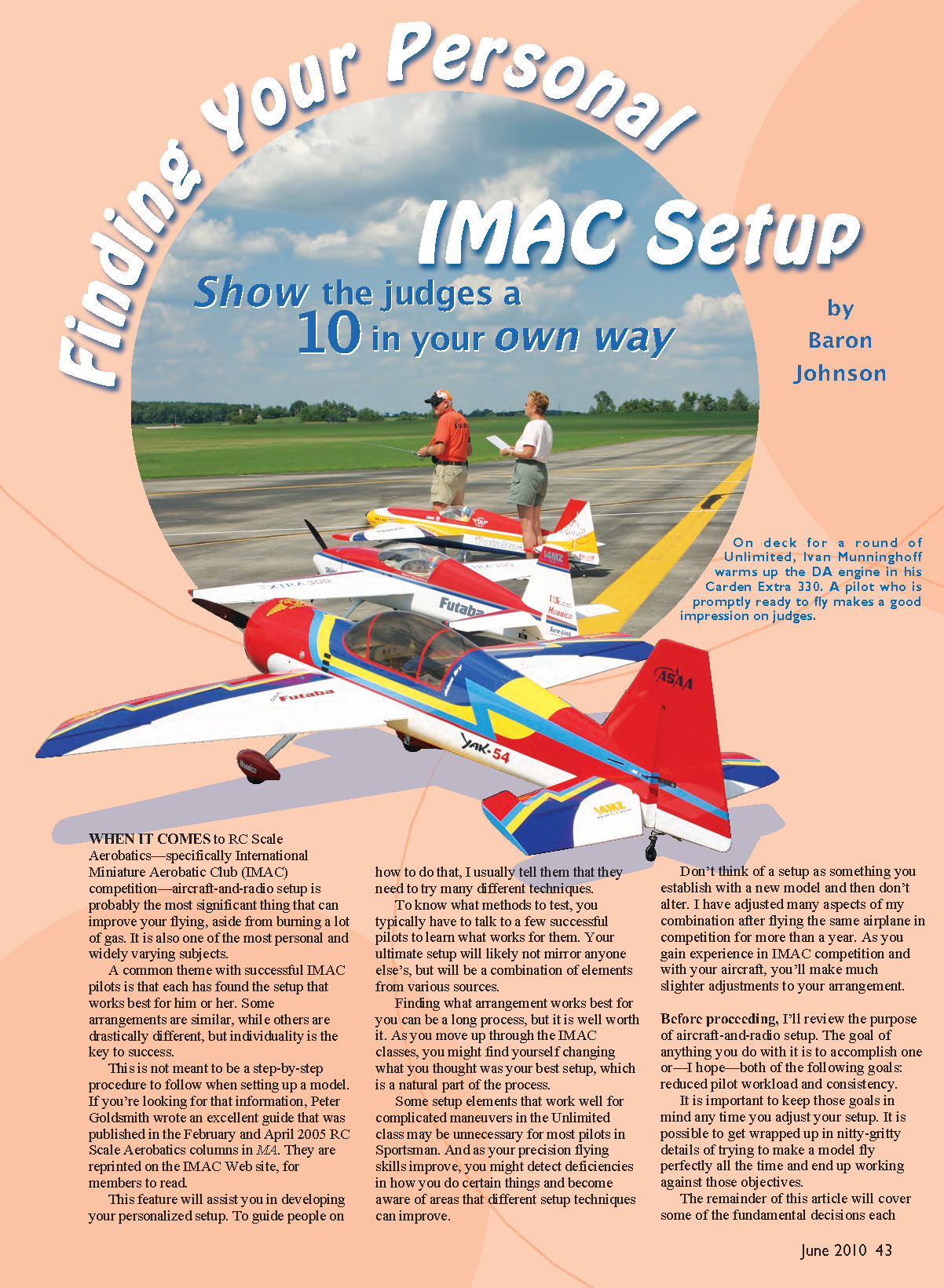
When it comes to RC scale aerobatics—specifically International Miniature Aerobatic Club (IMAC) competition—aircraft-and-radio setup is probably the most significant thing that can improve your flying, aside from burning a lot of gas. It is also one of the most personal and widely varying subjects.
A common theme with successful IMAC pilots is that each has found the setup that works best for him or her. Some arrangements are similar, while others are drastically different, but individuality is the key to success.
This is not meant to be a step-by-step procedure to follow when setting up a model. If you're looking for that information, Peter Goldsmith wrote an excellent guide that was published in the February and April 2005 RC Scale Aerobatics columns in Model Aviation (MA). They are reprinted on the IMAC website for members to read.
This feature will assist you in developing your personalized setup. To guide people on how to do that, I usually tell them that they need to try many different techniques.
To know what methods to test, you typically have to talk to a few successful pilots to learn what works for them. Your ultimate setup will likely not mirror anyone else's, but will be a combination of elements from various sources.
Finding what arrangement works best for you can be a long process, but it is well worth it. As you move up through the IMAC classes, you might find yourself changing what you thought was your best setup, which is a natural part of the process.
Some setup elements that work well for complicated maneuvers in the Unlimited class may be unnecessary for most pilots in Sportsman. And as your precision flying skills improve, you might detect deficiencies in how you do certain things and become aware of areas that different setup techniques can improve.
Don't think of a setup as something you establish with a new model and then never alter. I have adjusted many aspects of my combination after flying the same airplane in competition for more than a year. As you gain experience in IMAC competition and with your aircraft, you'll make much slighter adjustments to your arrangement.
Before proceeding, I'll review the purpose of aircraft-and-radio setup. The goal of anything you do with it is to accomplish one or—hopefully—both of the following goals: reduced pilot workload and consistency.
It is important to keep those goals in mind any time you adjust your setup. It is possible to get wrapped up in nitty-gritty details of trying to make a model fly perfectly all the time and end up working against those objectives.
The remainder of this article will cover some of the fundamental decisions each pilot must make when developing his or her setup. There is no right or wrong when it comes to these decisions; they are based purely on personal preference, and there are successful IMAC pilots who use all of these techniques.
I hope that discussing some of these decisions will allow you to test various setup methodologies and form your own setup, even if you don't have the opportunity to regularly talk with successful IMAC pilots.
Setup Objectives
- Reduced pilot workload.
- The less work you have to do, the more you can focus on other, finer aspects of a maneuver. A pilot has a seemingly endless list of things to concentrate on while flying precision aerobatics, so removing any of them through setup is a huge benefit.
- Consistency.
- This refers not only to how often you can properly execute a maneuver within a single contest or throughout the season, but also to how consistently you can perform the maneuver if you haven't practiced in a week or a month.
- Some approaches to setup can produce extremely good maneuvers when you execute them properly but can have severe consequences if they are not done perfectly for any number of reasons, such as lack of practice, nerves, or weather conditions. Envision how many snap rolls, spins, and hammerheads you'll perform throughout the course of a season!
Why Down-Line Mix?
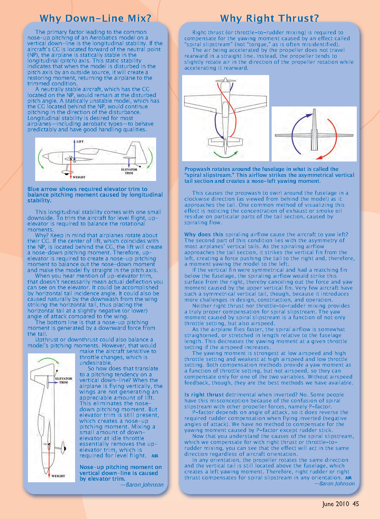
The primary factor leading to the common nose-up pitching of an aerobatics model on a vertical down-line is longitudinal stability. If the aircraft's center of gravity (CG) is located forward of the neutral point (NP), the airplane is statically stable in the longitudinal (pitch) axis. This static stability indicates that when the model is disturbed in the pitch axis by an outside source, it will create a restoring moment, returning the airplane to the trimmed condition.
A neutrally stable aircraft, with the CG on the NP, would remain at the disturbed pitch angle. A statically unstable model, with the CG behind the NP, would continue pitching in the direction of the disturbance. Longitudinal stability is desired for most airplanes—including aerobatic types—to behave predictably and have good handling qualities.
(This stability comes with one small downside: to trim the aircraft for level flight, up-elevator is required to balance the rotational moments.)
Why? Airplanes rotate about their CG. If the center of lift, which coincides with the NP, is located behind the CG, the lift will create a nose-down pitching moment. Therefore, up-elevator is required to create a nose-up pitching moment to balance out the nose-down moment and make the model fly straight in the pitch axis.
When you hear mention of up-elevator trim, that doesn't necessarily mean an observable deflection of the elevator. It could be accomplished by horizontal tail incidence angle or caused naturally by the downwash from the wing striking the horizontal tail, placing the horizontal tail at a slightly negative (or lower) angle of attack compared to the wing.
The bottom line is that a nose-up pitching moment is generated by a downward force from the tail.
Upthrust or downthrust could also balance a model's pitching moments; however, that would make the aircraft sensitive to throttle changes, which is undesirable.
So how does that translate to a pitching tendency on a vertical down-line? When the airplane is flying vertically, the wings are not generating an appreciable amount of lift. This eliminates the nose-down pitching moment while elevator trim (the up-elevator used for level flight) is still present, creating a nose-up pitching moment. Mixing a small amount of down-elevator at idle throttle essentially removes the up-elevator trim required for level flight.
Why Right Thrust?
Right thrust (or throttle-to-rudder mixing) is required to compensate for the yawing moment caused by an effect called "spiral slipstream" (not torque, as is often misidentified).
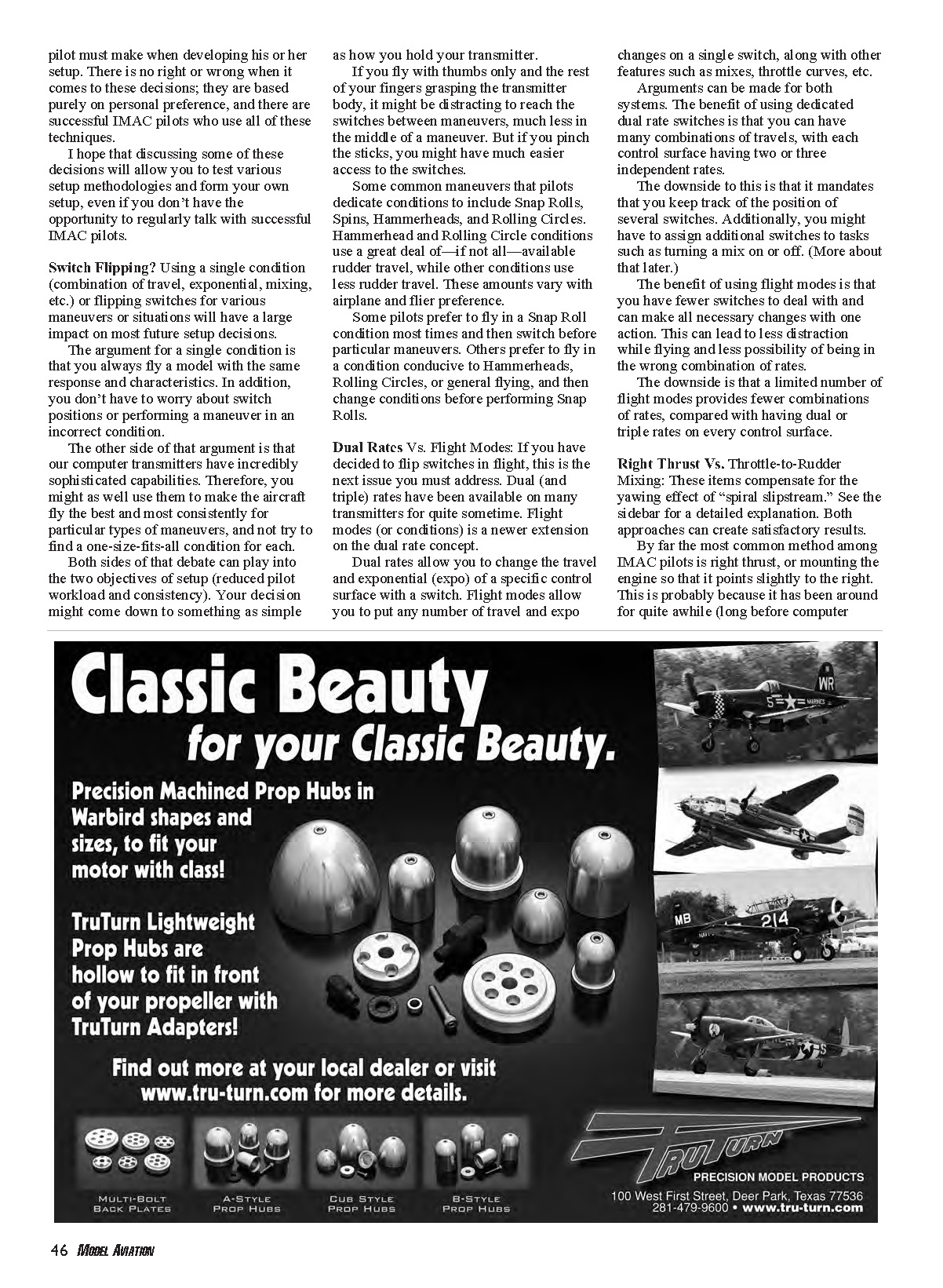
The air accelerated by the propeller does not travel rearward in a straight line. Instead, the propeller tends to slightly rotate the air in the direction of propeller rotation while accelerating it rearward. This propwash rotates around the fuselage in what is called the spiral slipstream. As that airflow strikes the asymmetrical vertical tail, it creates a nose-left yawing moment.
The spiraling airflow approaches the tail and tends to strike the vertical fin from the left, creating a force pushing the tail to the right and thereby yawing the model to the left. If the vertical fin were symmetrical with a matching fin below the fuselage, the spiraling airflow would strike from the right and cancel the upper fin's force; very few aircraft have such symmetry.
Neither right thrust nor throttle-to-rudder mixing provides a truly perfect compensation for spiral slipstream because the yaw moment caused by the slipstream is a function of both throttle setting and airspeed. As airspeed increases, the spiral airflow is somewhat straightened relative to fuselage length, decreasing the yawing moment at a given throttle setting. The yawing moment is strongest at low airspeed and high throttle setting and weakest at high airspeed and low throttle setting. Both right-thrust and throttle-to-rudder methods provide a yaw moment as a function of throttle only, so they can compensate for one variable but not both. Without airspeed feedback, they are the best methods we have available.
Is right thrust detrimental when inverted? No. Some people confuse spiral slipstream with other propeller forces, namely P-factor. P-factor depends on angle of attack and does reverse the required rudder compensation when flying inverted (negative angles of attack); that requires rudder stick input. Spiral slipstream, however, acts the same direction regardless of aircraft orientation because the propeller rotates the same way and the vertical tail remains above the fuselage. Therefore, right rudder or right thrust compensates for spiral slipstream in any orientation.
Switch Flipping?
Using a single condition (combination of travel, exponential, mixing, etc.) or flipping switches for various maneuvers or situations will have a large impact on most future setup decisions.
The argument for a single condition is that you always fly a model with the same response and characteristics. In addition, you don't have to worry about switch positions or performing a maneuver in an incorrect condition.
The other side of that argument is that our computer transmitters have incredibly sophisticated capabilities. Therefore, you might as well use them to make the aircraft fly the best and most consistently for particular types of maneuvers, and not try to find a one-size-fits-all condition for each.
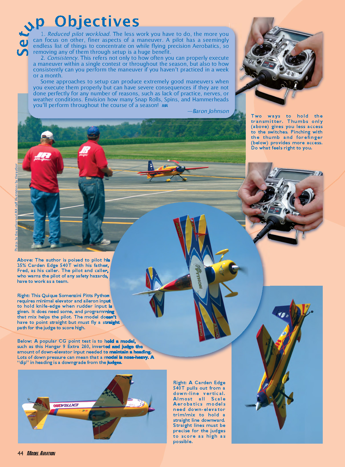
Both sides of that debate can play into the two objectives of setup (reduced pilot workload and consistency). Your decision might come down to something as simple as how you hold your transmitter. If you fly with thumbs only and the rest of your fingers grasping the transmitter body, it might be distracting to reach the switches between maneuvers, much less in the middle of a maneuver. But if you pinch the sticks, you might have much easier access to the switches.
Some common maneuvers that pilots dedicate conditions to include snap rolls, spins, hammerheads, and rolling circles. Hammerhead and rolling circle conditions use a great deal of—if not all—available rudder travel, while other conditions use less rudder travel. These amounts vary with airplane and flier preference.
Some pilots prefer to fly in a snap-roll condition most times and then switch before particular maneuvers. Others prefer to fly in a condition conducive to hammerheads, rolling circles, or general flying, and then change conditions before performing snap rolls.
Dual Rates vs. Flight Modes
If you have decided to flip switches in flight, this is the next issue you must address. Dual (and triple) rates have been available on many transmitters for quite some time. Flight modes (or conditions) are a newer extension of the dual-rate concept.
Dual rates allow you to change the travel and exponential (expo) of a specific control surface with a switch. Flight modes allow you to put any number of travel and expo changes on a single switch, along with other features such as mixes and throttle curves.
Arguments can be made for both systems.
- Benefit of dedicated dual-rate switches:
- You can have many combinations of travels, with each control surface having two or three independent rates.
- Downside:
- You must keep track of the position of several switches. You might also have to assign additional switches to tasks such as turning a mix on or off.
- Benefit of flight modes:
- Fewer switches to deal with; you can make all necessary changes with one action, leading to less distraction while flying and less possibility of being in the wrong combination of rates.
- Downside:
- A limited number of flight modes provides fewer combinations of rates compared with having dual or triple rates on every control surface.
Right Thrust vs. Throttle-to-Rudder Mixing
These items compensate for the yawing effect of spiral slipstream. Both approaches can create satisfactory results.
By far the most common method among IMAC pilots is right thrust—mounting the engine so that it points slightly to the right. This is probably because it has been around for quite a while (long before computer radios). Many models now come from their manufacturers with approximately correct right thrust built into the firewall.
The downside to right thrust is that to make changes you usually need to remove the cowling and add or remove spacers.
The other approach is mounting the engine straight and creating the required yaw moment by mixing right rudder with throttle position. This makes it easier to mount the power plant and exhaust, and it minimizes the eyesore of an offset spinner if the cowling is not shaped for it.
Throttle-to-rudder mix provides greater flexibility for changing the compensation to tweak it or to compensate for propeller changes. Additionally, most high-end transmitters allow you to do a curve mix, or nonlinear mix, which can help fine-tune the compensation throughout the throttle range (although not throughout the airspeed range).
Some pilots use a third approach: a combination of right thrust and throttle-to-rudder mixing. You can mount the engine with the manufacturer-specified right thrust or get it as close as possible and then make small adjustments with the transmitter. This methodology captures aspects of both original approaches but can be time-consuming.
Mixes: On All the Time?
This is a difficult question that pilots often ask as they add mixes to their setups. Some fliers turn off mixing—particularly down-line mixing—for landing so they don't get caught off-guard during approach.
In terms of within the sequence, the question is harder to answer. Some pilots advocate turning off some or all mixes for rolling circles or hammerheads, while many fliers leave all mixes on all the time.
This issue must be addressed on a model-by-model and mix-by-mix basis. With numerous airplanes I have had, I found no reason to turn off mixes for any maneuver. However, I have had models in which a mix was detrimental to certain maneuvers.
I had to fly maneuvers numerous times in different conditions before I could conclusively determine a mix as the cause. I ultimately reduced or eliminated the mixes in question to improve those particular maneuvers.
Judging from these experiences, I recommend planning on leaving mixes on all the time until you see a reason to do otherwise. Switching in and out of mixes adds a considerable workload if it's unnecessary.
Down-Line Mixing
Most statically stable aerobatic aircraft will exhibit a slight nose-up pitching tendency when placed on a power-off vertical down-line. This is one situation in which most IMAC pilots use the same setup principle: down-line mixing. Down-line mixing inputs a small amount of down-elevator when the throttle is reduced to idle or near idle (within a couple of ratchets).
The alternative, listed on some "trim charts," is to simply move the CG rearward until the pitch tendency goes away. This certainly eliminates that characteristic, but in doing so you move the CG to the neutral point, which eliminates longitudinal static stability.
A neutrally stable airplane will not fly well for most other precision maneuvers and will cause more headaches than mere down-line pitching. It is a small price to pay for a nice, stable model.
If you've never applied a mix such as this, there are numerous methods to accomplish the same thing with today's transmitters:
- Use a curve or nonlinear throttle-to-elevator mix and give it a value of zero at all points except near idle.
- Use a traditional throttle-to-elevator mix and employ the throttle position as the activation switch.
- Use a traditional throttle-to-elevator mix and utilize the offset function to effectively move the "center" point where the mix switches from one direction to the other. Offset it enough so that the mix activates at a couple of ratchets above idle. Leave the value activated by high throttle at zero mix and use the needed amount of mix on the idle side.
Closing Thoughts
This article has been anything but exhaustive. There are more methods to cover to address the preceding issues, and there are countless other issues that can be resolved with setup. I encourage you to explore other aspects of setup that you either learn from others or devise yourself.
I've tried to give a jump-start to those who don't have access to experienced IMAC pilots. However, no article can completely replace talking with other fliers and having them give you opinions, in person, about your setup.
If you are interested in competing in IMAC, find a contest near you and compete. You will probably learn more and get more advice—about both setup and flying—during that short event than you could from a year of practicing on your own. And you'll have a lot more fun!
Baron Johnson [email protected]
Sources:
- International Miniature Aerobatic Club: www.mini-iac.com
Transcribed from original scans by AI. Minor OCR errors may remain.

