
Flying DUTCHMAN
Phillip Kent
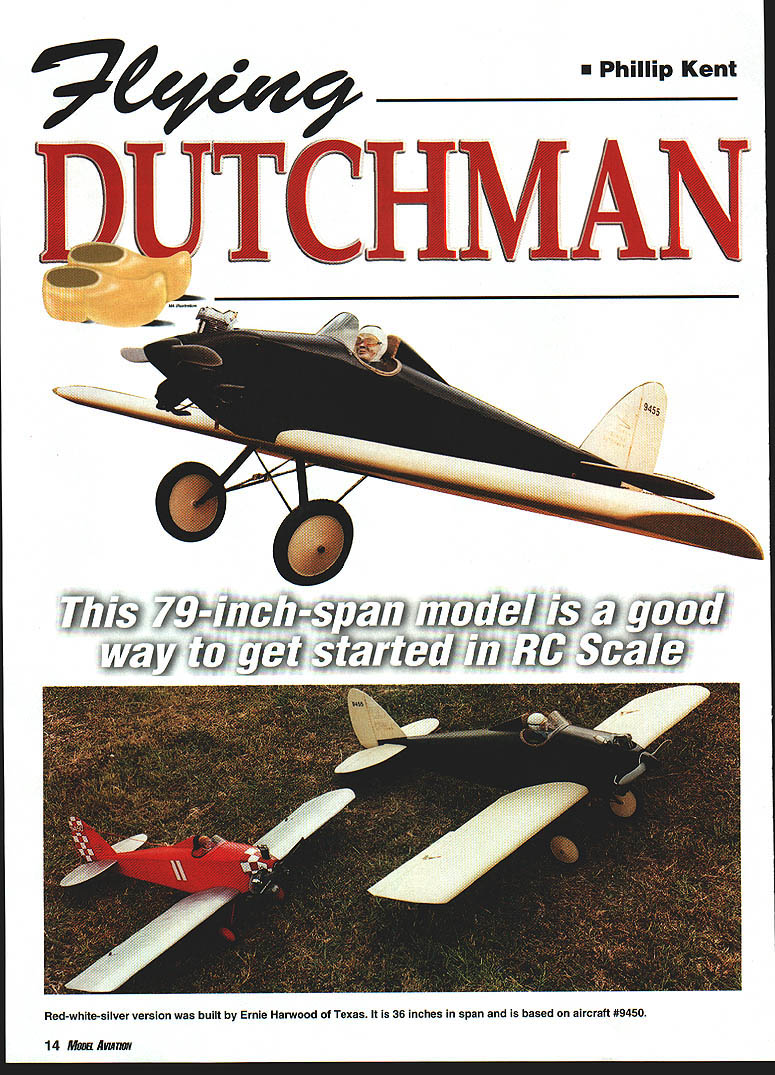
This 79-inch-span model is a good way to get started in RC Scale.
During the wave of aeronautical prosperity that resulted from the Lindbergh transatlantic flight in 1927, a large number of new aircraft companies were set up. Many of these companies did not last long; the Depression developed in the early 1930s, and after building only a few aircraft, the companies disappeared.
The Szekely company was unusual in that it built aircraft and engines. It is better known for the engines that it produced; these were much more successful than the aeroplanes.
In 1928 a three-cylinder engine, the SR-3, was put into production. It developed 40 hp at 1,800 rpm, with a weight of 148 pounds. A version of this engine, the SR-3-45, eventually powered several well-known designs that included the Curtiss-Wright Junior, Bull Pup, American Eagle, Spartan, Rearwin Junior, Prest Baby Pursuit, Nicholas Beazley NB-8, and Corben Baby Ace.
In 1929 the Szekely company announced the Flying Dutchman—a single-seat low-wing monoplane powered by the SR-3 engine. The aircraft was designed to fill the need for a small, light single-seater that had a good standard of construction with modest cost and economy of operation. Construction of the fuselage and tail surfaces was welded-steel tubing, fabric-covered.
The cantilever wooden wing was unusual in that it had no dihedral. It was claimed that the shape of the tips would allow the aircraft to maintain lateral stability without dihedral.
The undercarriage was of the split-axle type with rubber ring shock-absorbers. Because of the high-lift airfoil, it was claimed that the aircraft could take off in 75 feet. The top speed was 80 mph, with a landing speed of 25 mph. The advertised price was $2,200.
A production run of two aircraft per week was planned, but this never materialized because of the stock-market crash.
The information available about the full-size aircraft is sparse, so some color and detail choices are problematical. Nevertheless, the Flying Dutchman is a fun machine—enjoy it for what it is.
Philip S. Kent 32 Moorbottom Cleckheaton West Yorkshire BD19 6AD England
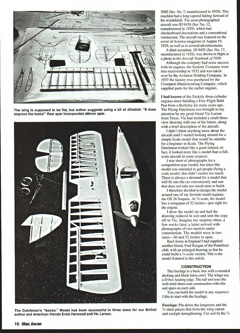
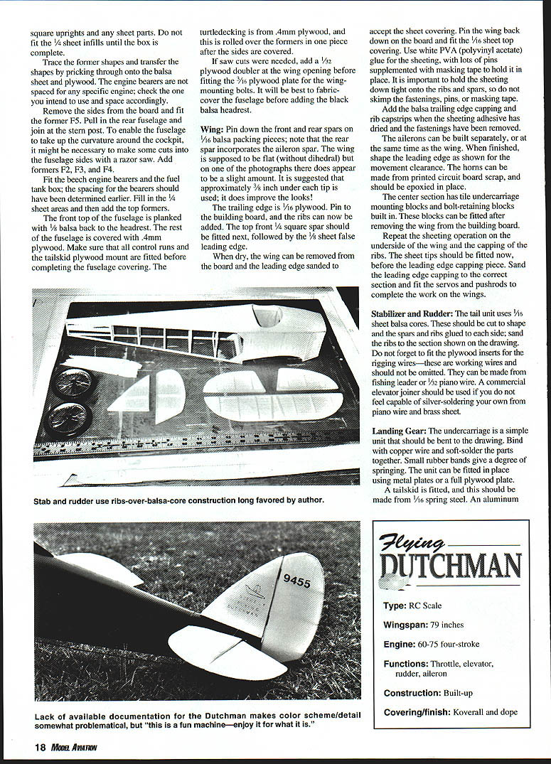
CONSTRUCTION
Fuselage:
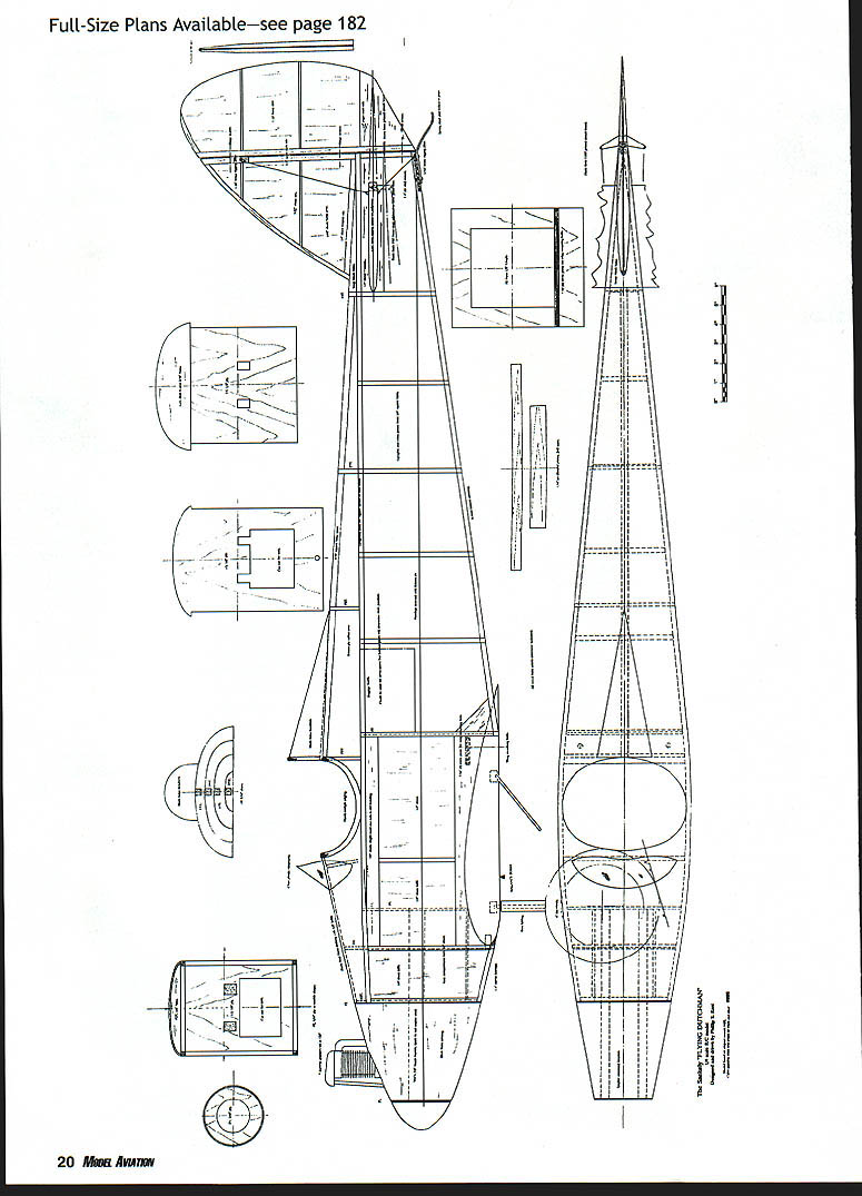
- Pin down the longerons and square uprights and any sheet parts. Do not fit the 1/4 sheet inlulls until the box is complete.
- Trace the former shapes and transfer them by pricking through onto the balsa sheet and plywood.
- The engine bearers are not spaced for any specific engine; check the one you intend to use and space accordingly.
- Remove the sides from the board and fit former F5. Pull in the rear fuselage and join at the stern post. To enable the fuselage to take up the curvature around the cockpit, it might be necessary to make some cuts into the fuselage sides with a razor saw. Add formers F2, F3, and F4.
- Fit the pegs, engine bearers, and the fuel tank box; the spacing for the bearers should have been determined earlier. Fill in the 1/4 sheet areas and then add the top formers.
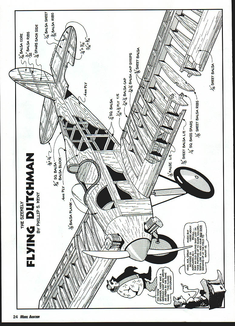
- The front top of the fuselage is planked with 1/8 balsa back to the headrest. The rest of the fuselage is covered with 0.4 mm plywood. Make sure that all control runs and the tailskid plywood mount are fitted before completing the fuselage covering.
- The turtledecking is from 0.4 mm plywood and is rolled over the formers in one piece after the sides are covered.
- If saw cuts were needed, add a 1/32 plywood doubler at the wing opening before fitting the 3/16 plywood plate for the wing-mounting bolts. It will be best to fabricate the fuselage before adding the black balsa headrest.
- A dowel was used for the front wing fixing in the full-size aircraft. It was fitted into the wing leading edge and a matching hole was made in the plywood former to ensure a snug fit of the wing when it is bolted in place.
- A pilot should be fitted in the cockpit, along with a simple instrument panel. The cockpit edging can be from rubber or plastic tubing or commercial cockpit edging.
Wing:
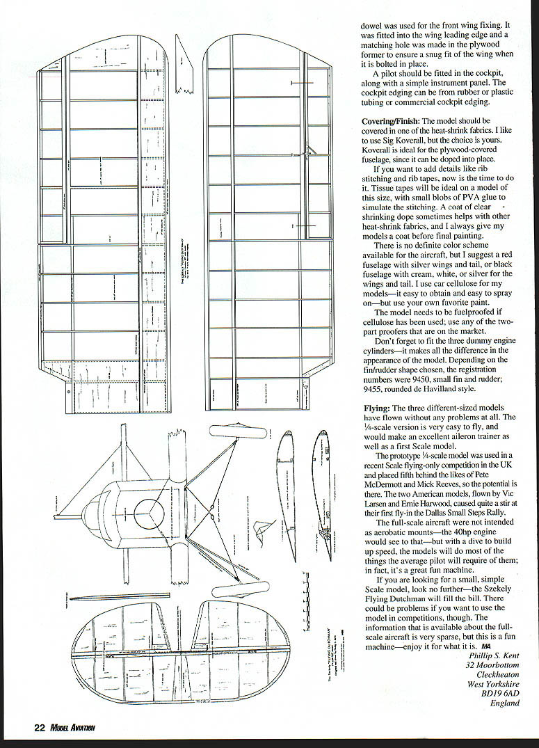
- Pin down the front and rear spars on 1/16 balsa packing pieces; note that the rear spar incorporates the aileron spar.
- The wing is supposed to be flat (without dihedral), but on one photograph there does appear to be a slight amount. It is suggested that approximately 3/8 inch under each tip is used; it does improve the looks.
- The trailing edge is 1/16 plywood. Pin to the building board, and add the ribs.
- Fit the top front 1/4 square spar next, followed by the 1/8 sheet false leading edge.
- When dry, remove the wing from the board and sand the leading edge to accept the sheet covering. Pin the wing back down on the board and fit the 1/16 sheet top covering.
- Use white PVA glue for the sheeting, with lots of pins supplemented with masking tape to hold it in place. Hold the sheeting tight onto the ribs and spars.
- Add the balsa trailing-edge capping and rib caps/strips when the sheeting adhesive has dried and the fastenings have been removed.
- The ailerons can be built separately or at the same time as the wing. When finished, shape the leading edge for movement clearance. The horns can be made from printed circuit board scrap and should be epoxied in place.
- The center section has undercarriage mounting blocks and bolt-retaining blocks built in. These can be fitted after removing the wing from the building board.
- Repeat the sheeting operation on the underside of the wing and cap the ribs. Fit the sheet tips before the leading-edge capping piece. Sand the leading-edge capping to the correct section and fit the servos and pushrods to complete work on the wings.
- A small dowel is used for the front wing fixing to ensure a snug fit when bolted in place.
Stabilizer and Rudder:
- The tail unit uses 1/16 sheet balsa cores. Cut to shape and glue spars and ribs to each side; sand the ribs to the section shown on the drawing.
- Fit the plywood inserts for the rigging wires—these are working wires and should not be omitted. They can be made from fishing leader or 1/32 piano wire.
- A commercial elevator joiner should be used if you do not feel capable of silver-soldering your own from piano wire and brass sheet.
Landing Gear:
- The undercarriage is a simple unit that should be bent to the drawing. Bind with copper wire and soft-solder the parts together. Small rubber bands give a degree of springing.
- The unit can be fitted in place using metal plates or a full plywood plate.
- A tailskid is fitted and should be made from 1/16 spring steel. An aluminum torque link is used between the leg and the skid to allow the skid to move if the model lands heavily.
Covering and Finish:
- The fuselage and flying surfaces were finished in Koverall and dope on the original.
- The model should be covered in one of the heat-shrink fabrics. Sig Koverall is recommended for the plywood-covered fuselage, since it can be doped into place.
- If you want to add details like rib stitching and rib tapes, now is the time to do it. Tissue tapes are ideal on a model of this size, with small blobs of PVA glue to simulate the stitching.
- A coat of clear shrinking dope sometimes helps with other heat-shrink fabrics; give the model a coat before final painting.
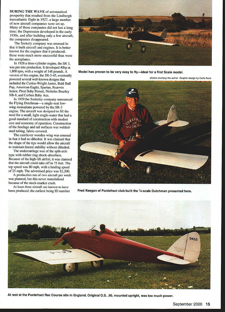
- Suggested color schemes: a red fuselage with silver wings and tail, or a black fuselage with cream, white, or silver wings and tail. Use your favorite paint; car cellulose is easy to obtain and spray on.
- The model needs to be fuelproofed if cellulose has been used; use any of the two-part proofers on the market.
- Don't forget to fit the three dummy engine cylinders—they make all the difference in appearance.
- Depending on the fin/rudder shape chosen, registration numbers used on full-size examples included 9450 (small fin and rudder) and 9455 (rounded de Havilland style).
FLYING
- The three different-sized models have flown without problems. The 1/4-scale version is very easy to fly and would make an excellent aileron trainer as well as a first Scale model.
- The prototype 1/4-scale model was used in a recent Scale flying-only competition in the UK and placed fifth, showing its potential.
- Two American models, flown by Vic Larsen and Ernie Harwood, caused quite a stir at their first fly-in, the Dallas Small Steps Rally.
- The full-size aircraft were not intended as aerobatic mounts—the 40 hp engine would see to that—but with a dive to build up speed, the models will do most of the things the average pilot will require of them. It's a great fun machine.
If you are looking for a small, simple Scale model, the Szekely Flying Dutchman will fill the bill. There could be problems if you want to use the model in competitions, though, because information about the full-size aircraft is sparse. Enjoy it for what it is.
Philip S. Kent
FLYING DUTCHMAN
BY PHILLIP S. KENT
Transcribed from original scans by AI. Minor OCR errors may remain.

