
Flying for Fun
D.B. Mathews
909 N. Maize Rd., Townhouse 734, Wichita KS 67212
In the midst of telephone conversations with Larry Sribnic of SR Batteries and Fred Marks of FMA Direct, something I'd never really considered came up: they find it difficult to sell battery packs or servos that require soldering on connectors. The simple truth is that many contemporary modelers don't know how to solder!
I have no evidence to support the theory, but I can't help but wonder if the root cause for this lack of an important and entertaining skill doesn't tie in with the inadequate devices sold in most stores as "soldering irons." I've been joining pieces of metal with solder for nearly 60 years, and I can't get satisfactory soldering results from those pistol-grip things. How can a novice possibly use one?
Well, that is not exactly fair; if one needed to repair a hole in a roof gutter or a water bucket, a pistol unit might be okay. But for anything requiring precision positioning and proper heating, those things make great doorstops.
The advantages of being capable of adding, changing, and repairing connectors on radio components are obvious. Many battery packs are supplied without connectors, servo connectors often break wires, or those supplied do not match the other equipment. Unfortunately we have never reached that dream of cross-compatible (or universal) connectors.
Not so many years ago, radio equipment was only available with the components and connectors sold separately. You were expected to wire each servo to a connector that plugged into another one to be installed coming out of the receiver. Additionally, switches were usually unwired, as were the battery packs. We learned to solder, or else. Even earlier than that, one bought loose components and soldered them to a board.
Even today, the art of soldering can save dollars and add to the reliability of the components. It's rather sad to see the number of servos, battery packs, and other devices discarded or removed from use because the owners have no soldering skills.
That lack of skills is unfortunate since soldering is not a particularly difficult technique. Once the principles are understood and the proper materials are assembled, soldering can be a fun project. In my opinion, soldering is less difficult than applying iron-on covering or installing a control system.
The Heat
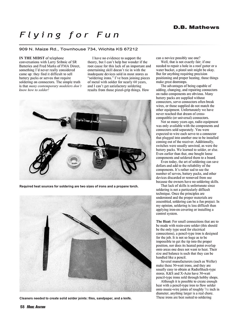
For small connections that are to be made with resin-core solder (this should be the only type used for electrical connections), a pencil-type iron is designed for the job. It is not so huge as to be impossible to get the tip into the proper position, nor does its heated point overlap onto areas one does not want to heat. Their size and balance is such that they can be handled like a pencil.
Several manufacturers (such as Weller) make these 30-watt irons, and they are usually easy to obtain at RadioShack-type stores. K&S and X-Acto have 30-watt pencil-type irons sold through hobby shops. Although it is possible to create enough heat with a pencil-type iron to flow solder onto music-wire joints of roughly 1/32 inch in diameter, anything larger is a real chore. These irons are best suited to soldering connectors and making joints in stranded radio-control wire.
On the other end of the heat scale are the larger units that resemble the pencil-type configuration but draw approximately 120 watts. These have wider, chisel-shaped tips and produce enough heat to flow acid-core solder along the joints of much heavier material than the 30-watt units. These irons obviously have much broader footprints and are capable of heating a wide area of a music-wire joint to flow the solder into the soft-wire wrapping and onto the wire itself. The heat on the tip is no higher than that produced with the pistol-grip, instant-heat units, but it is spread over a much wider area and the heat is more constant; therefore, they are vastly superior.
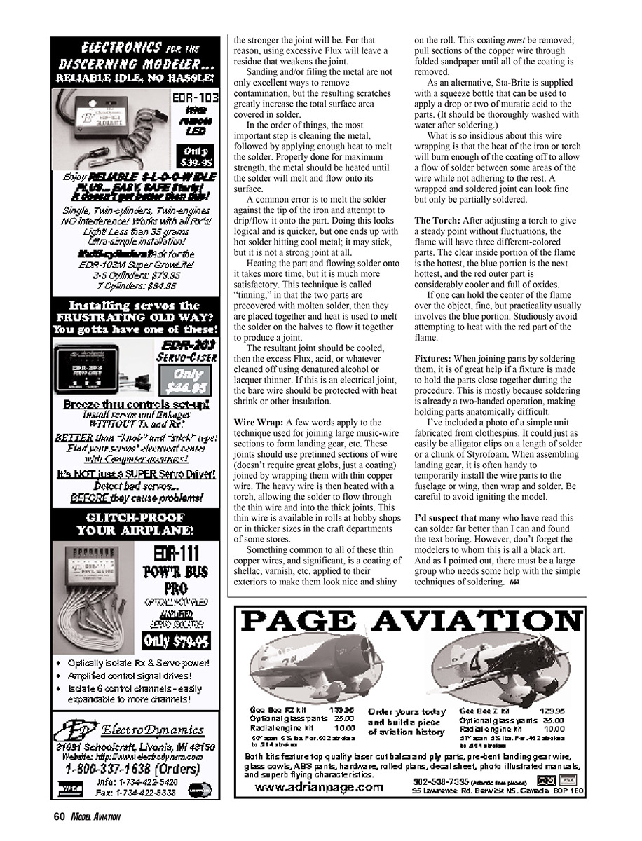
One disadvantage, albeit minor, is the large-tip pencil unit's much slower heating. However, this is not a problem if you plan for it; plug in the 120-watt unit before you need it. These things do get darn warm and should be rested on the supplied stand or some other type of heat sink between steps. An old glass ashtray or the side of a hammer will work well.
These 120-watt irons are ideal for soldering wire-landing-gear segments together, soldering links onto pushrods, and soldering washers onto the ends of music wire for wheel retainers, etc.
Types of Solder
The kind of solder you use is as important as the iron itself. Resin-core solder is mandatory for soldering electronic equipment. Never use acid-core solder on electronic devices! The acid will corrode and destroy the wiring and the components. Acid-core solder can be easily identified by its hollow center core filled with a jellylike substance.
On the other hand, it is difficult to successfully solder sections of metal or heavier wire using resin-core solder. This material is usually much thinner and more threadlike and has a solid center. It has a softer metal blend, melts at lower temperatures, and is the preferred solder for electronic connections.
A third type of heat source is the propane torch. These are sold under many names, but each uses a disposable tank and a knob-regulated fuel flow. They are for soldering jobs that require more strength than regular tin-lead solder provides and more heat than a 150-watt iron can produce. A small propane torch generates a large amount of heat at a temperature high enough to melt Sta-Brite and silver solder.
Don't fail to protect surrounding surfaces with wet towels or some other sort of heat shield when using an open-flame torch. It is much too easy to ignite something important.
Technique
What one is attempting to do is heat a clean metal object to a temperature sufficient to melt the solder and flow it along the exposed metal surfaces, then mate a second piece to the first by retinning the solder on the halves.
Key to those descriptions is the word "clean"; all metals interact with their surrounding environment to create a thin layer of contaminated metal on the surface. This layer is usually the result of atmospheric gases acting on the metal to form oxidation. However, dissimilar metals, moisture, and even the natural oils on our fingertips can contribute to corrosion. These corroded elements must be removed from the metal if there is to be a good flow of solder.
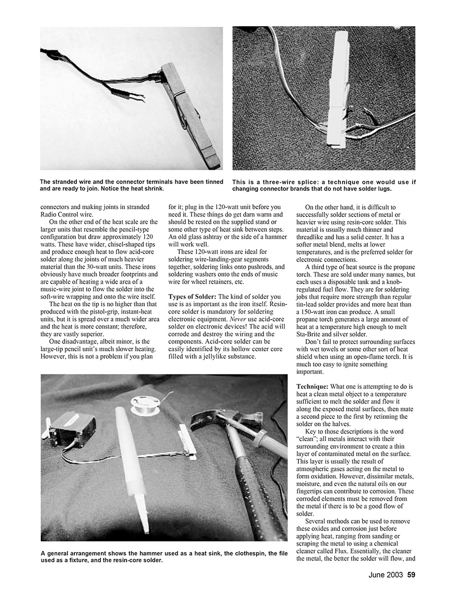
Several methods can be used to remove these oxides and corrosion just before applying heat, ranging from sanding or scraping the metal to using a chemical cleaner called flux. Essentially, the cleaner the metal, the better the solder will flow, and the stronger the joint will be. For that reason, using excessive flux will leave a residue that weakens the joint.
Sanding and/or filing the metal are not only excellent ways to remove contamination, but the resulting scratches greatly increase the total surface area covered in solder.
In the order of things, the most important step is cleaning the metal, followed by applying enough heat to melt the solder. Properly done for maximum strength, the metal should be heated until the solder will melt and flow onto its surface.
A common error is to melt the solder against the tip of the iron and attempt to drip or flow it onto the part. Doing this looks logical and is quicker, but one ends up with hot solder hitting cool metal; it may stick, but it is not a strong joint at all.
Heating the part and flowing solder onto it takes more time, but it is much more satisfactory. This technique is called "tinning," in that the two parts are precovered with molten solder, then they are placed together and heat is used to melt the solder on the halves to flow it together to produce a joint.
The resultant joint should be cooled, then the excess flux, acid, or whatever cleaned off using denatured alcohol or lacquer thinner. If this is an electrical joint, the bare wire should be protected with heat shrink or other insulation.
Wire Wrap
A few words apply to the technique used for joining large music-wire sections to form landing gear, etc. These joints should use pretinned sections of wire (doesn't require great globs, just a coating) joined by wrapping them with thin copper wire. The heavy wire is then heated with a torch, allowing the solder to flow through the thin wire and into the thick joints. This thin wire is available in rolls at hobby shops or in thicker sizes in the craft departments of some stores.
Something common to all of these thin copper wires, and significant, is a coating of shellac, varnish, etc. applied to their exteriors to make them look nice and shiny on the roll. This coating must be removed; pull sections of the copper wire through folded sandpaper until all of the coating is removed.
As an alternative, Sta-Brite is supplied with a squeeze bottle that can be used to apply a drop or two of muriatic acid to the parts. (It should be thoroughly washed with water after soldering.)
What is so insidious about this wire wrapping is that the heat of the iron or torch will burn enough of the coating off to allow a flow of solder between some areas of the wire while not adhering to the rest. A wrapped and soldered joint can look fine but only be partially soldered.
The Torch
After adjusting a torch to give a steady point without fluctuations, the flame will have three different-colored parts:
- The clear inside portion of the flame is the hottest.
- The blue portion is the next hottest and is what you will most often use to heat parts.
- The red outer part is considerably cooler and full of oxides; avoid heating with this part.
If one can hold the center of the flame over the object, fine, but practicality usually involves the blue portion. Studiously avoid attempting to heat with the red part of the flame.
Fixtures
When joining parts by soldering them, it is of great help if a fixture is made to hold the parts close together during the procedure. This is mostly because soldering is already a two-handed operation, making holding parts anatomically difficult.
I've included a photo of a simple unit fabricated from clothespins. It could just as easily be alligator clips on a length of solder or a chunk of Styrofoam. When assembling landing gear, it is often handy to temporarily install the wire parts to the fuselage or wing, then wrap and solder. Be careful to avoid igniting the model.
I'd suspect that many who have read this can solder far better than I can and found the text boring. However, don't forget the modelers to whom this is all a black art. And as I pointed out, there must be a large group who needs some help with the simple techniques of soldering.
MA
Transcribed from original scans by AI. Minor OCR errors may remain.

