

A complete RC float-flying primer!
D.B. Mathews | [email protected]
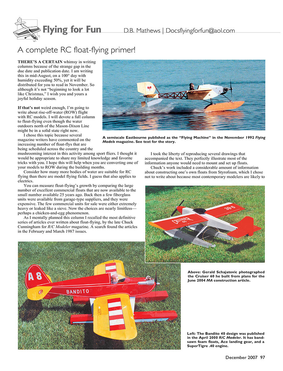
There’s a certain whimsy in writing columns because of the strange gap between the due date and publication date. I am writing this in mid-August on a 100° day with humidity exceeding 50%, yet it will be distributed for you to read in November. So although it’s not “beginning to look a lot like Christmas,” I wish you and yours a joyful holiday season.
If that’s not weird enough, I’m going to write about rise-off-water (ROW) flight with RC models. I will devote a full column to float-flying even though the water outdoors north of the Mason–Dixon Line might be in a solid state right now.
I chose this topic because several magazine writers have commented on the increasing number of float-flys being scheduled across the country and the mushrooming interest in this activity among sport fliers. I thought it would be appropriate to share my limited knowledge and favorite tricks with you. I hope this will help when you are converting one of your models to ROW during the building months. Consider how many more bodies of water are suitable for RC flying than there are model flying fields. I guess that also applies to electrics.
You can measure float-flying’s growth by comparing the large number of excellent commercial floats that are now available to the small number available 25 years ago. Back then a few fiberglass units were available from garage-type suppliers, and they were expensive. The few commercial units for sale were either extremely heavy or leaked like a sieve. Now the choices are nearly limitless—perhaps a chicken-and-egg phenomenon.
As I mentally planned this column I recalled the most definitive series of articles ever written about float-flying, by the late Chuck Cunningham for R/C Modeler magazine. A search found the articles in the February and March 1987 issues.
I took the liberty of reproducing several drawings that accompanied the text. They perfectly illustrate most of the information anyone would need to mount and set up floats.
Chuck’s work included a considerable amount of information about constructing one’s own floats from Styrofoam, which I chose not to write about because most contemporary modelers are likely to purchase some of the excellent float units. As I mentioned, 25 years ago one was forced to construct floats from scratch since few were available commercially. If you would like to review Chuck’s instructions for constructing floats, you can contact the AMA library for copies of the articles.
What You Need to Know
If you have looked at the drawings, you may have noticed that the step (the notch on the bottom of the float) should be placed roughly 1/2 inch aft (behind) the balance point — close to where the wheel axles would be on a conventional-wheeled tail-dragger. Additionally, the float length should be approximately 75% of the fuselage length measured from the back of the propeller to the rudder hinge line. Width is indicated on the drawing for various-size powerplants.
A handy rule of thumb: the model should float without sinking and should settle so that about 20% of the float height remains above the water. If it doesn’t, the floats are probably too big.
As I’ve written many times through the years, if your land-based model is adequately powered with a .40 engine, you may need to substitute a .60 for float-flying. Why? First, floats add considerably to your model’s overall weight. Second, all that stuff hanging out there produces a considerable increase in parasitic drag. Also, to avoid the need for a retrieval boat or a long wait for the wind to push your model ashore, its engine must sustain a reliable idle.
By the way, these models kick up a considerable amount of spray, and that will eat up a wooden propeller pronto! Therefore, the propeller arc should be about 4 inches behind the tips of the floats.
That spray problem also means you must waterproof the receiver and batteries by encasing them in plastic wrap or clear supermarket produce bags. Close them with tie wraps. There is really no way to isolate servos completely from moisture, so be prepared to dry them by disassembling if the model becomes submerged after a crash.
If the engine is submerged, immediately dry it off as well as you can. Remove the plug and the fuel line, and spin the engine awhile with your starter. When the engine is no longer spitting out water, rehook the fuel and plug and run it for a tank full. Give the metal parts a good shot of lubricant and you should have no damage. I take a hair dryer to float-flying events so I can thoroughly dry the inside of a model after a day’s flying.
Floats actually improve pitch and roll stability on a given model (tail-dragger or tricycle gear). This fits the old Charles Grant rule that the more mass there is below a model’s center of lift, the more stable it will be — consider a high-wing aircraft versus a low-winged aircraft.
However, enlarged vertical fins or ventral fins are needed on some airplanes because that mass hanging down tends to require additional area to prevent yaw (side-to-side) motions. This seems particularly true for full-scale or model Cub types and some others.
On the other hand, turning the model will usually require more rudder deflection, but aileron rolls accelerate from the top down — sort of neat to look at.
Installing Floats
Most commercial float kits include adequate installation instructions, so I’ll just toss in a couple of my favorite points.
A wide variety of preformed aluminum or carbon-fiber landing-gear units is available at your local hobby shop or by mail order. Get a pair for simplicity’s sake. I strongly recommend these instead of the bent-wire units we used to use.
Steel axles are perfect with these units. I also prefer to use the nylon nose-gear blocks (some may need to be sawn into pieces) that several manufacturers sell to mount the steel axles to the top of the floats. Quality wheel collars will retain the brackets on the axles and allow for some adjustment — that is, if the floats you are using have hardwood blocks in the appropriate locations.
These hardwood blocks are much stronger and add more resistance to side-to-side motion than the nylon gear mounts, which are also sold as accessories. Through the years the most common area of failure I’ve observed is the mounting of the gear to the floats.
If necessary, epoxy plywood across the inside fuselage bottom, behind the wing leading and trailing edges. Don’t skimp on this step; the floats transmit considerable twisting and shear forces to these mounts. I like to use #6 sheet-metal screws (SMS) to secure the landing gear to the fuselage.
I prefer to block up floats on the building surface until their tops are level. Use a spirit level, not your eyeballs. Then use a premarked location on the fuselage to indicate where the model balanced with wheels. This is still the balance point on floats, but you may need to add weight to the nose or tail to balance the model after installation.
Locate the floats relative to the balance point; measure midline to midline of the floats, making sure they are pointed straight ahead; then mark and drill into the hardwood blocks for sheet-metal screws to secure the nose-gear blocks. Floats mounted toe-in or toe-out can produce wild gyrations on takeoff and landing.
Most model designs have the fuselage bottom tapered rearward at the wing trailing edge, so it is usually necessary to shim the rear landing-gear leg to the fuselage bottom. The wing must be set at a slight positive angle (leading edge up) or you will end up with a strange-looking hydroplane.
I used to feel the need for crossbraces running from float top to float top. That was apparently needed for flimsy vacuum-formed floats on wire gear, and I no longer bother.
Steering
This aspect of float-flying brings out modelers’ ingenuity. I have observed some way-out-there setups. I prefer the simple approach: a piece of tin sheet soldered onto a piece of wire and hung off the rudder. It looks a bit odd, but you can’t beat it for ease.
More aesthetically pleasing are the Ernst and Top Flite units that are hinged to the back of the floats and driven by either cable or bellcrank in the fuselage, attached to the rudder horn with a pushrod. With those, the motion is carried through the fuselage bottom via a torque system to another series of horns and pushrods. If you have a waterproof servo, consider mounting it to the fuselage bottom and running cable-type rod in nylon sleeves to the water rudders.
The first time I flew a model off water was in Gunnison, Colorado, with longtime friend Paul Schlegel and his 4-40 BiPe on his homemade foam floats. He based them on ancient free-flight floats he found in a magazine. And we did not have a water rudder! This was in 1984.
We flew our aircraft off a pond and tried our best to taxi back to shore, but if an engine died on the water we just waited for the breeze to drift the model ashore. Who needed a water rudder or a retrieval boat? However, I can’t recommend not using a system for steering the model on the water.
Flying on Floats
It is ideal to start on a shore that allows you to take off directly into the wind so you can use the drift-ashore trick I mentioned. You can taxi from anywhere to get the nose into the wind if need be.
Do not “horse” the model off the water! I see this far too often, and the result is the same as on land except exaggerated. Accelerate until the model gets “on step” on its own and then gently apply up-elevator to break out of the water. Torque is torture, and the same takeoff principles apply as for a wheeled model.
Landings are identical, except the float model is much heavier and draggy, so approach speed should be higher and the approach longer. Throttle back slowly, keep the wings level, stay off the elevator, and you should see a lovely sliding sort of landing.
Caption Additions / Anecdotes
The Eastbourne (Flying Machine) was a learning experience for me. I originally constructed foam floats that rotted out in a few years. My “designer” curved them at the stern and tapered the sides. The film I used to cover the floats was Monokote and it did an OK job but did not hold up as well as fiberglass. I subsequently laminated balsa to the foam with epoxy and glass cloth for reinforcement. The Eastbourne flew well but the floats leaked a little. The lesson: use proven commercial floats or use good sealing techniques.
Following the design of the 1911 prototype, although the model would get on step, as you can see in the photo, it was a chore to get it there and usually required a judicious application of down-elevator.
In the early years of flying, designers used a half-float with a tail float. Apparently that worked for the period, but I found that it took forever to get the model onto the step. That’s because the starting position left the nose and wing at such a steep positive angle that the model struggled to get into a flying position.
Later I changed to full-length, scratch-built floats, and the Eastbourne flew much nicer. It had a broken-loose aileron servo rail at an ACE float-fly years ago, and I didn’t discover it until later. It turned to the right fine, but left turns were awful.
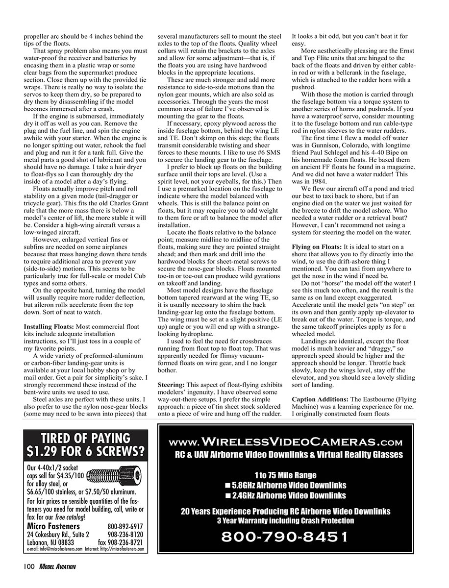
The Bandito 40 used homemade foam floats following Chuck Cunningham’s parameters, and I flew it until it became so waterlogged that I threw it away. It was one of my all-time favorites.
The Ace Seamaster kit has been a favorite of float-flyers for many years. It is a floatplane as opposed to an airplane on floats. The factory staff enlarged the design to 120 size, and it proved to be a wild airplane.
The crew asked me to look at it later to see if I could figure out why it flew so poorly. After roughly an hour of scratching my head, it dawned on me what might be wrong. Ken Willard designed the original 40-size model and it used a typical Willard flat, fully symmetrical airfoil. The enlarged version used the existing kit ribs and other parts from my 4-120’s wing. The design team then attempted to use the balance point of Ken’s wing on my semisymmetrical section. His wing balanced at 25% and mine at 35%. The enlarged model they were flying was viciously nose-heavy!
George Knapple built the Ace Whiz 40 shown more than 16 years ago. He took out all but 1° of wing incidence, powered it with a K&B .65, and flew it a lot on wheels. George crashed the model and gave it to Steve Dockery, who repaired it and put it in a pair of Lanier floats using the kit’s wide-track, formed-aluminum landing gear. This setup has been flown — very well — hundreds of times.
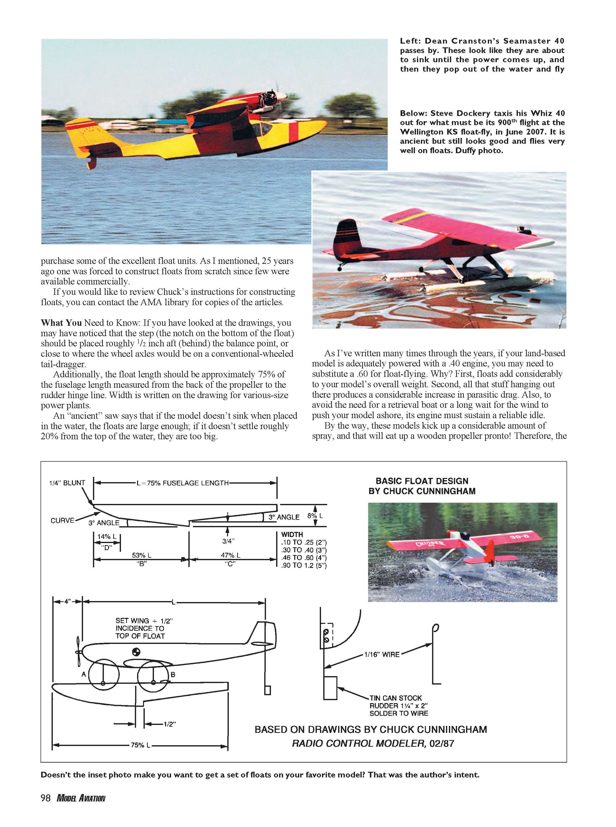
The Cruiser 60 construction article was published in the June 2004 Model Aviation. Gerald Schajatovic of Chesterland, Ohio, built his from the magazine plans, powered it with an O.S. .60 engine, and used Goldberg floats.
Of the 76 designs I’ve had published, the Cruiser 60 is far and away the best one never to be kitted.
Enough of this; go put an RC model in the water, get your socks wet, and fly for fun.
Transcribed from original scans by AI. Minor OCR errors may remain.

