
Flying for Fun
D.B. Mathews | [email protected]
Correcting previous information about an Airtronics receiver
OOPS! In the February 2007 column I wrote some erroneous information. In an effort to correct that, I'll try again.
Old-style Airtronics receivers will run satisfactorily on any negative-shift transmitter, and some of the newer Futaba and Hitec transmitters have the capability of changing shifts. Thus old-style (and new-style for that matter) Airtronics receivers can be run with any transmitter that is capable of changing shift.
Back when transmitters were either positive or negative shift, Airtronics receivers would only respond to Airtronics or JR transmitters. Now that many transmitters come with the ability to be set for either shift, this is no longer a problem.
If you have an old Airtronics transmitter and want the advantages of programmability, etc., you can purchase a modern Airtronics transmitter to get what you want. Airtronics may have transmitters that are capable of selecting frequencies or soon will. However, there is a catch. The leads from old Airtronics servos are wired differently. To work with modern Airtronics and other servos, the leads must be changed or a suitable "jumper" must be installed. The JR9303 transmitter I mentioned is still a good alternative since the frequency can be changed to match the various Airtronics receivers you want to use. One transmitter can run all the various frequencies of your old Airtronics flight packs.
I hope this clarifies what I wrote. I have never owned Airtronics equipment and was repeating what the only local flier who is using it told me, but the story wasn't straight. The incompatibility of the servos somehow got twisted around to an incompatibility of the whole system. I made the error of repeating an old wives' tale without checking the facts.
Also included in this column:
- The Pterodactyl
- Stearman-Hammond revisited
More Odd Aircraft
The highly gratifying reader response to my seeking out how much interest there is in prototypes that have been rarely, if ever, modeled leads me to base another column on that subject. It has become obvious that many of us enjoy playing "Do you know this airplane?" with our friends. The Internet provides us with access to a nearly unlimited supply of information about aircraft prototypes that fall into the "What on earth is that thing?" classification. Nearly all people are driven throughout their lives to add to their funds of knowledge, whether practical or trivial. The Internet is a hyperfast research tool compared to the old-fashioned encyclopedia and library-card searches.
The Pterodactyl
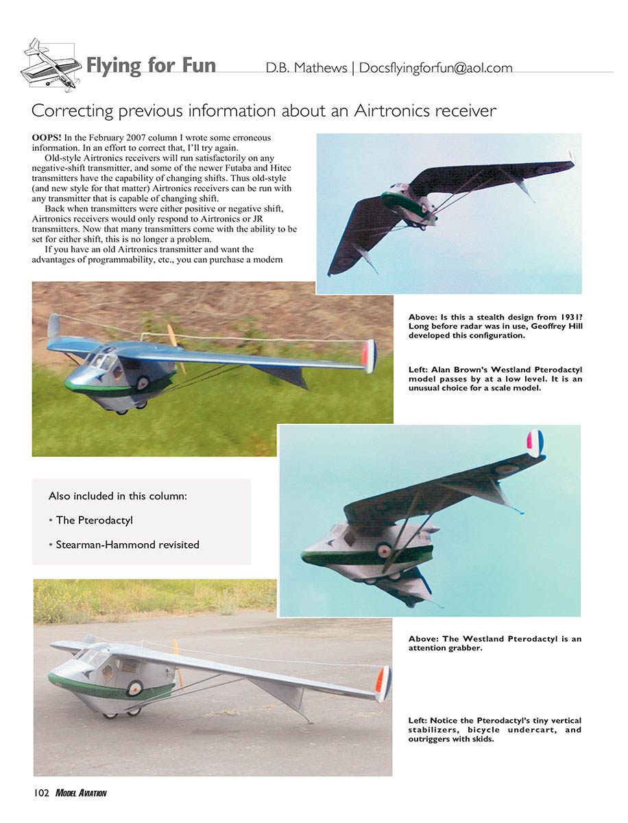
Named for its resemblance to the prehistoric flying reptiles, the tailless Pterodactyl aircraft was designed by Captain Geoffrey Hill. He was Handley Page's chief test pilot in 1918 and advanced to work on the famous Handley Page wing slots. On his own Hill had designed and constructed a tailless glider he first flew at Devils Rest Bottom on the Sussex Downs in December 1924. It was a study in maintaining control of tailless aircraft when stalled. The Pterodactyl and subsequent versions were highly successful; they could not be stalled. The Air Ministry and the Royal Aircraft Establishment were impressed and funded an order for a version to be powered with a 35-horsepower Bristol Cherub engine. And although Hill was on the Handley Page staff, Westland was chosen to take over the project. During the ensuing eight years Westland and Hill designed and built several additional Pterodactyl prototypes, including a tractor-engined two-seat fighter with a machine-gun turret in the back.
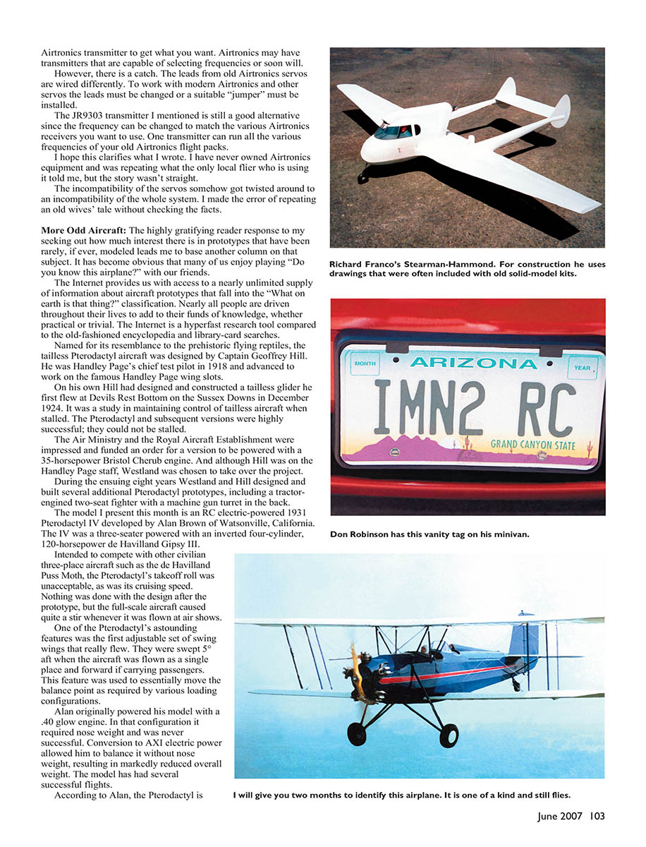
The model I present this month is an RC electric-powered 1931 Pterodactyl IV developed by Alan Brown of Watsonville, California. The IV was a three-seater powered with an inverted four-cylinder, 120-horsepower de Havilland Gipsy III.
Intended to compete with other civilian three-place aircraft such as the de Havilland Puss Moth, the Pterodactyl's takeoff roll was unacceptable, as was its cruising speed. Nothing was done with the design after the prototype, but the full-scale aircraft aroused quite a stir whenever it was flown at air shows.
One of the Pterodactyl's outstanding features was the first adjustable set of swing wings that really flew. They were swept 5° aft when the aircraft was flown as a single place and forward if carrying passengers. This feature was used to essentially move the balance point as required by various loading configurations.
Alan originally powered his model with a .40 glow engine. In that configuration it required nose weight and was never successful. Conversion to AXI electric power allowed him to balance it without nose weight, resulting in markedly reduced overall weight. The model has had several successful flights.
According to Alan, the Pterodactyl is horrible on takeoff. If you use too little throttle, one of the wingtip fin/skids will dig in and cause it to ground loop. If you give it too much power, the high thrustline combined with the short longitudinal track bicycle gear causes it to nose over.
Alan’s model is 1/6 scale, which gives it an 88-inch wingspan. Construction is conventional stick and sheet.
He has no workable drawings for his model but is willing to advise anyone who would like to enlarge the three-views in Westland Aircraft Since 1925 by Derek N. James and build a Pterodactyl IV. Several FF (free-flight) rubber-powered Pterodactyl designs have been published through the years.
If you have the urge to develop such a strange model, consider the three-views and information about the Pterodactyl IB in The Book of Westland Aircraft by A. H. Lukens, published by Harborough Publishing Ltd.
Neither of these books was in file at my local library, but the staff used an interlibrary loan on the Internet to get them from other libraries.
Stearman-Hammond Revisited
When I featured the Ariel in the December 2006 column I mentioned that someone had to have built a flyable model of this interesting prototype since a large number of photos and articles about it are available from various sources. But there is not much in the way of three-views.
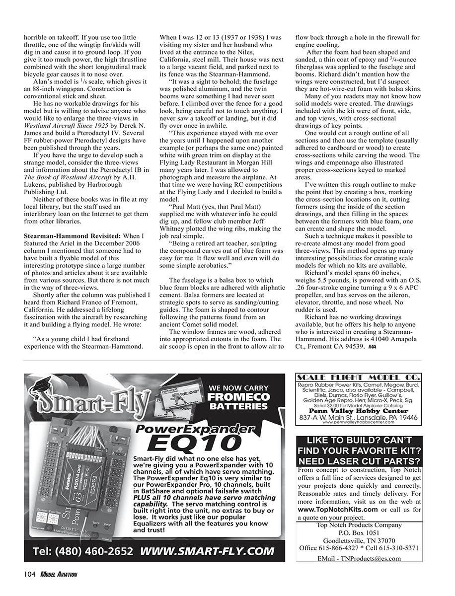
Shortly after the column was published I heard from Richard Franco of Fremont, California. He addressed a lifelong fascination with the aircraft by researching it and building a flying model. He wrote:
“As a young child I had firsthand experience with the Stearman-Hammond. When I was 12 or 13 (1937 or 1938) I was visiting my sister and her husband who lived at the entrance to the Niles, California, steel mill. Their house was next to a large vacant field, and parked next to its fence was the Stearman-Hammond.
“It was a sight to behold; the fuselage was polished aluminum, and the twin booms were something I had never seen before. I climbed over the fence for a good look, being careful not to touch anything. I never saw a takeoff or landing, but it did fly over once in awhile.
“This experience stayed with me over the years until I happened upon another example (or perhaps the same one) painted white with green trim on display at the Flying Lady Restaurant in Morgan Hill many years later. I was allowed to photograph and measure the airplane. At that time we were having RC competitions at the Flying Lady and I decided to build a model.
“Paul Matt (yes, that Paul Matt) supplied me with whatever info he could dig up, and fellow club member Jeff Whitney plotted the wing ribs, making the jig real simple.
“Being a retired art teacher, sculpting the compound curves out of blue foam was easy for me. It flew well and even will do some simple aerobatics.”
The fuselage is a balsa box to which blue foam blocks are adhered with aliphatic cement. Balsa formers are located at strategic spots to serve as sanding/cutting guides. The foam is shaped to contour following the patterns found from an ancient Comet solid model.
The window frames are wood, adhered into appropriate cutouts in the foam. The air scoop is open in the front to allow air to flow back through a hole in the firewall for engine cooling.
After the foam had been shaped and sanded, a thin coat of epoxy and 3/4-ounce fiberglass was applied to the fuselage and booms. Richard didn’t mention how the wings were constructed, but I’d suspect they are hot-wire-cut foam with balsa skins.
Many of you readers may not know how solid models were created. The drawings included with the kit were of front, side, and top views, with cross-sectional drawings of key points.
One would cut a rough outline of all sections and then use the template (usually adhered to cardboard or wood) to create cross-sections while carving the wood. The wings and empennage also illustrated proper cross-sections keyed to marked areas.
I’ve written this rough outline to make the point that by creating a box, marking the cross-section locations on it, cutting formers using the inside of the section drawings, and then filling in the spaces between the formers with blue foam, one can create and shape the model.
Such a technique makes it possible to re-create almost any model from good three-views. This method opens up many interesting possibilities for creating scale models for which no kits are available.
Richard’s model spans 60 inches, weighs 5.5 pounds, is powered with an O.S. .26 four-stroke engine turning a 9 x 6 APC propeller, and has servos on the aileron, elevator, throttle, and nose wheel. No rudder is used.
Richard has no working drawings available, but he offers his help to anyone who is interested in creating a Stearman-Hammond. His address is 41040 Amapola Ct., Fremont, CA 94539.
MA
Transcribed from original scans by AI. Minor OCR errors may remain.

