
Flying for Fun
D.B. Mathews
909 N. Maize Rd., Townhouse 734, Wichita KS 67212
LIKE FINE WINE:
I'm constructing an SR Batteries Cutie. In the midst of this project, it has occurred to me how incredibly time has improved model-airplane kits and their construction.
Long before my time, model airplanes were constructed from bamboo and hardwood (usually spruce or pine).
If one looks at the drawings for these "twin pusher," etc. designs of the 1920s, it becomes obvious that adhesives were also primitive. Often the parts were glued, nailed together with small brads, then the joints were wrapped with thread.
According to Frank Zaic, the earliest source of balsa wood was shipping crates used for baker's yeast. Some of the earliest model-supply businesses were built around the availability of dimensionally cut balsa from those boxes.
Nitrocellulose glue represented another major advance in construction. It was initially created by dissolving surplus nitrate photographic film in acetone. How many of the now-extinct early movie prints might have been destroyed this way?
In the ensuing years, adhesives based on butyrate (Ambroid, etc.), aliphatic resins (Sig Bond, etc.), and epoxies came into use in modeling.
In 1973 Bob and Bill Hunter introduced cyanoacrylate (CA) adhesives with their Hot Stuff and forever changed the way models are built.
Kits of that era were often supplied with sheet wood with patterns printed on them. One laboriously cut each part from these sheets—no small task.
I've been told, but have never been able to verify, that some kits had die-cut parts pre-1942, notably the Comet Sailplane, the Clipper, and the Zipper.
I do know that the prewar Jim Walker Fireball kit came with a router-shaped block fuselage, band-sawn tail group, and wing ribs. The wartime kits often "featured" die-cut paper formers.
In the post-World War II modeling boom, many kits featured die-cut parts. To say this represented a huge improvement over cutting the parts with a knife is an understatement. Many of the kits today still use die-cutting very successfully.
Die-cutting is an interesting process and perhaps even an art form. A few firms specialized in creating dies by imbedding thin strips of sharp metal in a rubber base to match the designer's drawings.
This plate or die is then installed in a flatbed-printing or similar press, placing the balsa, softened by aging in a high-humidity environment, on the opposite flat surface, and the die is pressed through the wood into a rubber plate.
The quality and accuracy of die-cutting is much affected by wood density and grain, the press's ability to bring the plate down flat on the wood sheet, and the sharpness of the imbedded blades.
This humidifying process explains why die-cut parts invariably have the grain raised. I can tell you from personal experience that die-cutting parts is less than an exact science. Many sheets are unusable in a kit run and must be discarded.
When designing a kit that will be die-cut, one has to allow a fudge factor dimensionally to compensate for the fuzzy outside edges, which must be sanded smooth. The same holds true for spar notches, which need to be designed slightly tight to compensate for the necessary sanding.
Another factor to consider in a die-cut kit is amortization of the cost of the metal dies; they are expensive. To justify setting up a die-cut kit run, one must produce many kits to recover the die-maker's costs and the time required to set the press for each set of parts.
The process is also rather slow and labor-intensive. It is not possible to stack-cut several layers of sheet.
Although many kits are still die-cut, the latest and greatest by far are those with laser-cut parts. The part patterns are scanned into a computer program, which guides a thin beam of high-frequency light through the wood to create a part.
The accuracy of this technique is not much affected by the factors I mentioned for die-cutting.
The first laser-cut kit I saw was from Herr Engineering. When I opened the box and saw the shrink-wrapped sheets with dark outlines of the parts, I honestly thought the thing had printed sheets!
Imagine my astonishment and delight when I started flexing the sheets, and the parts fell out. Only a quick swipe with fine sandpaper to remove the blackened outlines is needed.
One limiting factor for laser-cutting is the thickness and density of the wood stock. It is possible to laser-cut balsa as thick as 3/8 inch, but the amount of energy (heat) required burns a larger area, and there is some danger of igniting it.
An alternative to laser-cutting thick parts is the water jet. This device uses a thin stream of water under extreme pressure to cut the material. With this system it is possible to cut even heavy metal parts. However, I am unaware of any water-jet-cut model-airplane kits.
Many of the contemporary custom kit-cutters still supply kits of the shaped parts that are usually band-sawn and sanded or router-cut. These "short" kits are supplied without strip or flat sheet wood.
In some instances (such as with All American Kit Cutters) one purchases the plans from another source, but some kits, such as those from Klarich Old Timers, also supply the plans.
Recently, several custom kit-cutters have started marketing kits of laser-cut parts. The advantage is that a small run of kits, or even a single kit, can be cut with minimum setup effort. One scans the drawings into the program, slips the correct disk into a computer, selects and positions the wood, and turns on the laser-cutter.
A couple of companies that handle custom laser-cutting are Bob Holman Plans and Threshold CAD.
If you're relatively new to this hobby, you can't fully appreciate the accuracy of laser-cutting — no crunched pieces and slots for stringers that fit so accurately and the parts stay together before applying the adhesive. You never had it so good!
Now model-airplane-kit designers can create and design parts that would have been impossible to fabricate without laser-cutting. The SR Cutie kit has so many innovations that the word "inspired" keeps popping into my head.
The following will detail some of this "inspired innovation," but for openers consider wing-dihedral braces made from laser-cut Lexan® sheet.
The wing uses a leading edge and main spar of fiberglass tube. Die-cutting round holes accurately is nearly impossible, but the fit is right on with laser-cutting. The same holds true for the little plywood sections that hold the cabane tubes onto the wing saddle and inside the fuselage.
Can you imagine how these holes would look if they were die-cut from plywood?
These tube retainers are inserted in slots in the saddles, which fit so well one must remember to glue them.
Designer Larry Sribnick has very cleverly utilized the advantages of laser-cutting to solve a perplexing construction problem peculiar to parasol models. His cabane-strut system creates a very accurate, strong, and easily assembled unit.
Larry freely admits to being influenced by the Lee-Renaud-designed Airtronics QT kit of the 1970s, as I was when I enlarged the QT to .15 to .23-size and published it as the My Oh My in the April 1980 Radio Control Modeler.
In both instances, the best we could do was use strips of hardwood horizontal and vertical members assembled over the plans, trying for as much accuracy as possible when inserting them into the fuselage.
Do you see why I feel that the Cutie is inspired?
I'm quite sure other laser-cut kits now available take full advantage of the potentials inherent in laser-cut parts. It's reasonable to say we are entering a new era in model-airplane kits.
Political Correctness:
My friends in the aircraft industry tell me that a device designed to hold various parts in position while they are being assembled is no longer referred to as a "jig" but rather a "fixture."
The reason in this age of political correctness is self-explanatory. The Cutie, then, uses some of the cleverest fixtures for its assembly I've ever encountered. The accompanying photos show some of the fixtures but require further explanation.
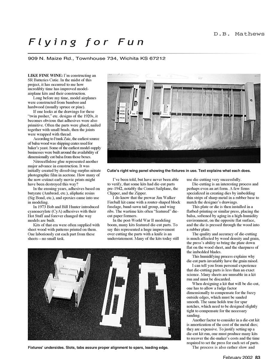
The Cutie's wing (as is that of the SR Batteries X250) is built on a flat surface using four blocks of balsa, which have been drilled and screwed into pairs of clamps to hold the leading-edge and mainspar fiberglass tubes level while the ribs and sheeting are added.
The ribs are slid over the rods, then the whole thing is clamped flat. Fixtures of laser-cut parts are used to set the dihedral angle at the center rib, and space the ribs properly and at right angles to the rods.
Sections of paper clip and rubber bands are used to hold the leading edge in position, then all the joints are touched with CyA to glue them in place.
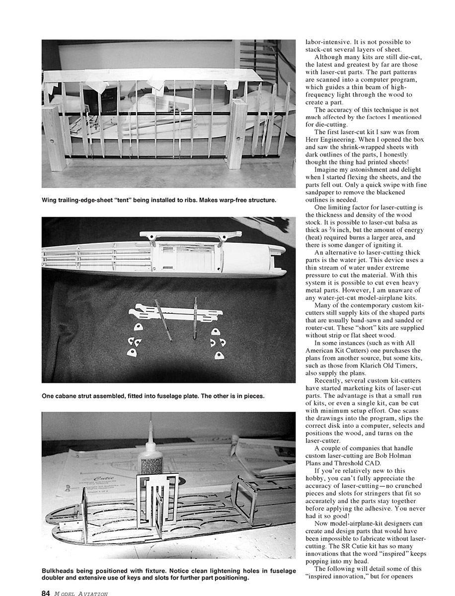
These fixtures have tabs on the bottom side to hold them square with the tubes. In the photo of the right wing panel, the fixture on the left has a 90° setting on the inside face and a dihedral angle on the terminal rib side.
Next is a fixture that spaces and aligns the center-section ribs, then another that does the same for the other ribs.
Notice the clamps tightened on the rods and the rubber-band/paper-clip devices being used to hold the leading edge tight against the ribs. The trailing-edge sheeting is not added until the basic structure has been set on its nose.
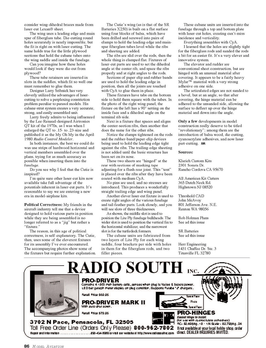
These two sheets are "hinged" at the rear with sections of masking tape adjusting for a flush rear joint. This "tent" is placed over the ribs after they have been coated with medium CyA.
No pins are used, and no stresses are introduced. This produces a wonderfully straight trailing edge and wing panel.
Another clever laser-cut fixture is used to create right angles of the various fuselage and tail-feather parts. Look closely, and you will see slots of three thicknesses.
As shown, the middle slot is used to position the Lite Ply fuselage bulkheads. The wider slot is used to position the vertical fin to the horizontal stabilizer, and the narrowest slot is for the turtledeck formers.
The cabane units are fabricated from two layers of Lite Ply for each wing saddle, four brackets per side with holes in them for the fiberglass rods, and two filler pieces.
These cabane units are inserted into the fuselage through a top and bottom plate with laser-cut holes, creating can't-miss incidence and verticality.
Everything assembles with CyA.
I learned that the holes are slightly tight for the fiberglass rods and sanded the rods a bit for an easier fit. It's a very clever and innovative system.
The elevator and rudder are conventional sheet construction, but are hinged with an unusual material after covering. It appears to be a fairly heavy Mylar™ material with a very strong adhesive on one side.
The articulated edges are not sanded to a bevel, but at an angle, so that after covering, the hinge material can be adhered to the unsanded side, allowing the surface to deflect up over the hinge material and down into the angle.
Only a few developments in model construction really deserve to be titled "revolutionary"; among them are the introduction of balsa wood, die-cutting, cyanoacrylate adhesives, and now laser part-cutting.
Sources:
- Klarich Custom Kits
2301 Sonata Dr. Rancho Cordova CA 95670
- All American Kit Cutters
365 Dutch Neck Rd. Hightstown NJ 08520
- Threshold CAD
John McAvoy 801 Jefferson Ave. N.E. Renton WA 98056
- Bob Holman Plans
See ad this issue
- SR Batteries
See ad this issue
- Herr Engineering
1431 Chaffee Dr. Ste. 3 Titusville FL 32780
Transcribed from original scans by AI. Minor OCR errors may remain.

