
Flying With Realism
by Ralph Grose
The ability to fly a model airplane in a smooth, precise, scale-like manner without erratic motion is a skill for which many of us strive. However, airplanes have a few inherent characteristics that tend to inhibit smooth, exact control. If the pilot is aware of these and understands how to compensate, he or she can do a more realistic job of flying the aircraft.
The normal level turn will be more realistic if the pilot can smoothly roll the airplane to the desired bank angle, hold the angle constant throughout the turn with no climbing, diving, skidding, or slipping, and then smoothly roll back to straight and level flight.
A skidding turn is a situation where the turn rate is too fast for the angle of bank. The airplane will skid to the outside of the turn, similar to the way a race car would skid while turning too fast on a moderately banked track.
A slipping turn is a case where the turn rate is too slow for the angle of bank. The airplane will slip sideways toward the inside of the turn; it may or may not lose altitude in the process. You can recognize a slipping turn when you view it from the ground: the wing on the outside of the turn (the high wing) will hang back, and the airplane’s nose will be pointed slightly above the horizon.
Primary flight controls
The three primary flight controls are elevator, ailerons, and rudder:
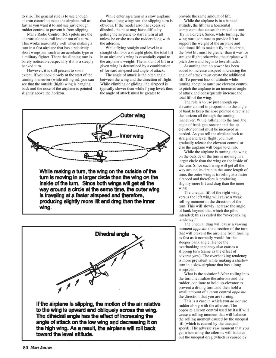
- The elevator is used to pitch the airplane about its lateral axis.
- The ailerons are used to roll the airplane about its longitudinal axis.
- The rudder is used to yaw the airplane about its normal axis.
The three axes intersect at the airplane’s center of gravity.
The control functions overlap. As the pilot uses the ailerons while entering a turn, one aileron moves down and the other moves up. This produces a differential in lift between the right and left wings, which causes the airplane to roll to the banked attitude.
The aileron that moves down causes drag in that wing to increase. The aileron that moves up may reduce drag for a small movement and then increase drag for a larger movement. In any case, there will be a differential in drag between the wings, which will cause the airplane to yaw in a direction opposite to the roll. This is called adverse yaw because when the pilot uses the ailerons, as a rule he or she does not want the airplane to yaw in the opposite direction.
While rolling to a banked attitude at the beginning of a turn, adverse yaw will prevent the airplane from turning as fast as it normally would for a given angle of bank. This causes it to start a slipping turn.
The method to correct for adverse yaw is to use the rudder in the same direction as the ailerons — right rudder with right aileron, left rudder with left aileron. The rudder will cause a yawing moment in the direction of the turn that balances the adverse yaw moment.
It takes practice to coordinate the two controls. Too much rudder will cause the airplane to skid; not enough will allow it to slip. The general rule is to use enough aileron to make the airplane roll as fast as you want and just enough rudder to prevent slipping.
Many radio-control (RC) pilots use the ailerons alone to roll into or out of a turn. This works reasonably well in a fast airplane with a relatively short wingspan, such as an aerobatic type or a military fighter; the slipping turn is barely noticeable, especially in a steeply banked turn. However, it is still present to some extent. If you look closely at the start of the maneuver, you can see the outside (high) wing hanging back and the nose pointed slightly above the horizon.
While entering a turn in a slow airplane with a long wingspan, the slipping turn is obvious. If the model also has excessive dihedral, the pilot may have difficulty getting the airplane to start a turn at all unless he or she uses the rudder along with the ailerons.
Lift, angle of attack, and turning
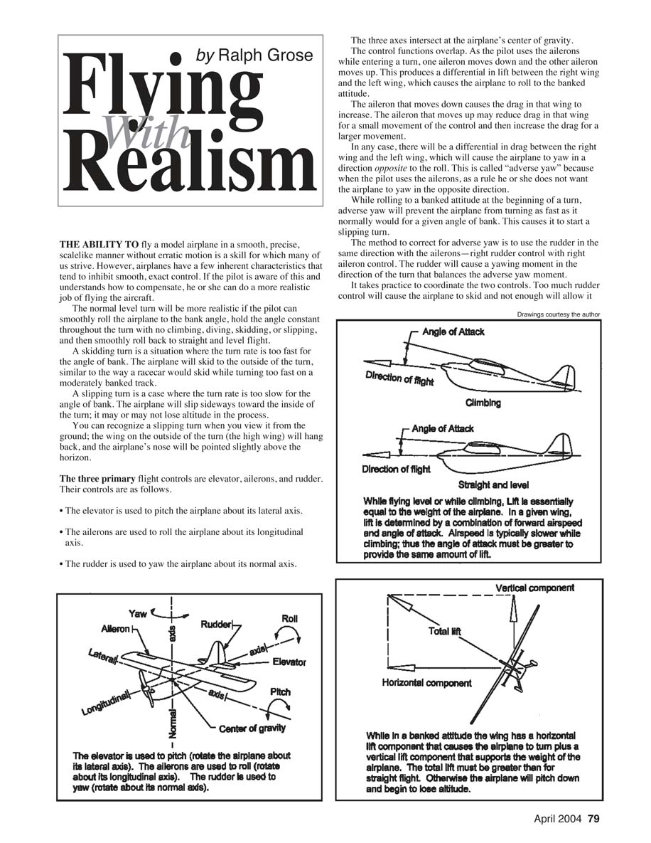
While flying straight and level, the total lift from the wings is essentially equal to the airplane’s weight. Lift is determined by a combination of forward airspeed and angle of attack. Angle of attack is the pitch angle between the wing and the direction of flight. During climbs or glides the airspeed is typically slower than when flying level; thus the angle of attack must be greater to provide the same lift.
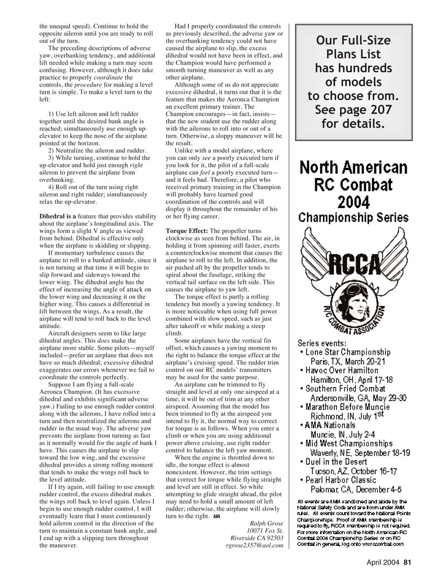
While the airplane is banked, the lift vector has a horizontal component that causes the aircraft to turn. Since the wing must continue to provide lift to support the weight and additional lift to sustain the turn, the total lift must be greater than in straight flight; otherwise the airplane will pitch down and lose altitude.
Assuming no power is added to increase airspeed, increasing the angle of attack must create the additional lift. To prevent loss of altitude while turning, the pilot must use elevator control to increase the angle of attack and thus increase total lift.
The rule is to use just enough up-elevator in proportion to the angle of bank to keep the nose pointed at the horizon throughout the maneuver. While rolling into the turn, increase up-elevator as needed. As you roll back to straight and level flight, gradually release the elevator or the airplane will begin to climb.
Overbanking tendency
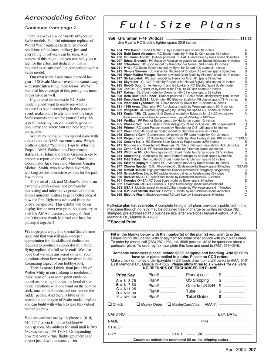
While turning, the outside wing travels in a larger circle than the inside wing. Since both wings complete their circles in the same time, the outside wing moves faster and therefore produces slightly more lift and drag than the inside wing.
The unequal lift produces a weak rolling moment in the direction of the turn that will slowly increase the angle of bank beyond what the pilot intended; this is the overbanking tendency.
The unequal drag produces a yawing moment opposite the direction of the turn that will prevent the airplane from turning as fast as it would for the steeper bank angle. Hence, the overbanking tendency also contributes to a slipping turn. This tendency is more prevalent in shallow turns in slow airplanes with long wingspans.
Solution: after rolling into the turn, neutralize the ailerons and rudder, continue to hold up-elevator to prevent a dive, and then hold a small amount of aileron opposite the direction of the turn.
In this case you do not use rudder with the ailerons. The opposite aileron will create a rolling moment that balances the rolling moment caused by unequal lift. The adverse yaw from that aileron input will balance the unequal drag caused by the unequal speeds. Continue to hold the opposite aileron until you are ready to roll out of the turn.
The procedure for making a level turn to the left is:
- Use left aileron and left rudder together until the desired bank angle is reached; simultaneously use enough up-elevator to keep the nose pointed at the horizon.
- Neutralize the aileron and rudder.
- While turning, continue to hold up-elevator and hold just enough right aileron to prevent the airplane from overbanking.
- Roll out of the turn using right aileron and right rudder; simultaneously relax the up-elevator.
Dihedral
Dihedral provides stability about the airplane's longitudinal axis. The wings form a slight V angle as viewed from behind. Dihedral is effective only when the airplane is skidding or slipping.
If momentary turbulence causes the airplane to roll to a banked attitude while not turning, it will begin to slip forward and sideways toward the lower wing. The dihedral angle increases the angle of attack on the lower wing and decreases it on the higher wing, creating a differential lift that tends to roll the airplane back to level.
Aircraft designers often favor large dihedral angles because they increase stability. Some pilots prefer less dihedral; excessive dihedral exaggerates errors when controls are not perfectly coordinated.
For example, in a full-scale Aeronca Champion (which has pronounced dihedral and significant adverse yaw), failing to use enough rudder with the ailerons can cause repeated slipping: the aircraft will slip toward the low wing, the strong dihedral will roll the wings back toward level, and the pilot may end up holding aileron into the turn continuously to maintain bank. Proper coordination of aileron, rudder, and elevator prevents adverse yaw or overbanking from inducing a slip, so the Champion performs a smooth turn and acts as an effective primary trainer. A pilot trained in such an airplane is likely to develop good coordination habits that serve throughout their flying career.
Torque Effect
The propeller turns clockwise as seen from behind. The air, in holding it from spinning faster, exerts a counterclockwise moment that tends to roll the airplane to the left. In addition, the air pushed aft by the propeller tends to strike the vertical tail surface on the left side, causing the airplane to yaw left.
The torque effect is partly a rolling tendency but mostly a yawing tendency. It is more noticeable when using full power at slow speed, such as just after takeoff or during a steep climb.
Some airplanes have the vertical fin offset to produce a right yawing moment that balances the torque effect at cruising speed. Rudder trim on RC transmitters can be used similarly.
An airplane can be trimmed to fly straight and level at only one airspeed at a time; it will be out of trim at other speeds. Assuming the model has been trimmed for the intended airspeed, the normal correction for torque is: when you enter a climb or use additional power, apply right rudder to balance the left yaw moment.
When the engine is throttled down to idle, the torque effect is almost nonexistent. However, the trim settings that corrected for torque in straight-and-level flight remain in effect, so during a glide the pilot may need to hold a small amount of left rudder; otherwise the airplane will slowly turn right.
Ralph Grose 10071 Fox St. Riverside, CA 92503 [email protected]
Transcribed from original scans by AI. Minor OCR errors may remain.

