
FMS P-51B MUSTANG
Jay Smith [email protected]
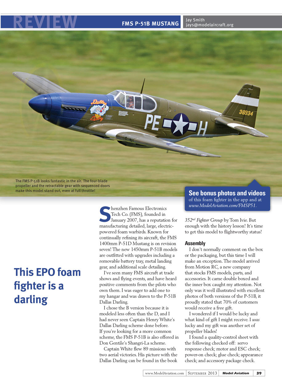
Shenzhen Famous Electronics Tech Co. (FMS), founded in January 2007, has a reputation for manufacturing detailed, large, electric-powered foam warbirds. Known for continually refining its aircraft, the FMS 1400mm P-51D Mustang is on revision seven! The new 1450mm P-51B models are outfitted with upgrades including a removable battery tray, metal landing gear, and additional scale detailing.
I've seen many FMS aircraft at trade shows and flying events, and have heard positive comments from the pilots who own them. I was eager to add one to my hangar and was drawn to the P-51B Dallas Darling.
I chose the B version because it is modeled less often than the D, and I had never seen Captain Henry White's Dallas Darling scheme done before. If you're looking for a more common scheme, the FMS P-51B is also offered in Don Gentile's Shangri-La scheme.
Captain White flew 89 missions with two aerial victories. His picture with the Dallas Darling can be found in the book 352nd Fighter Group by Tom Ivie. But enough with the history lesson! It's time to get this model to flightworthy status!
Assembly
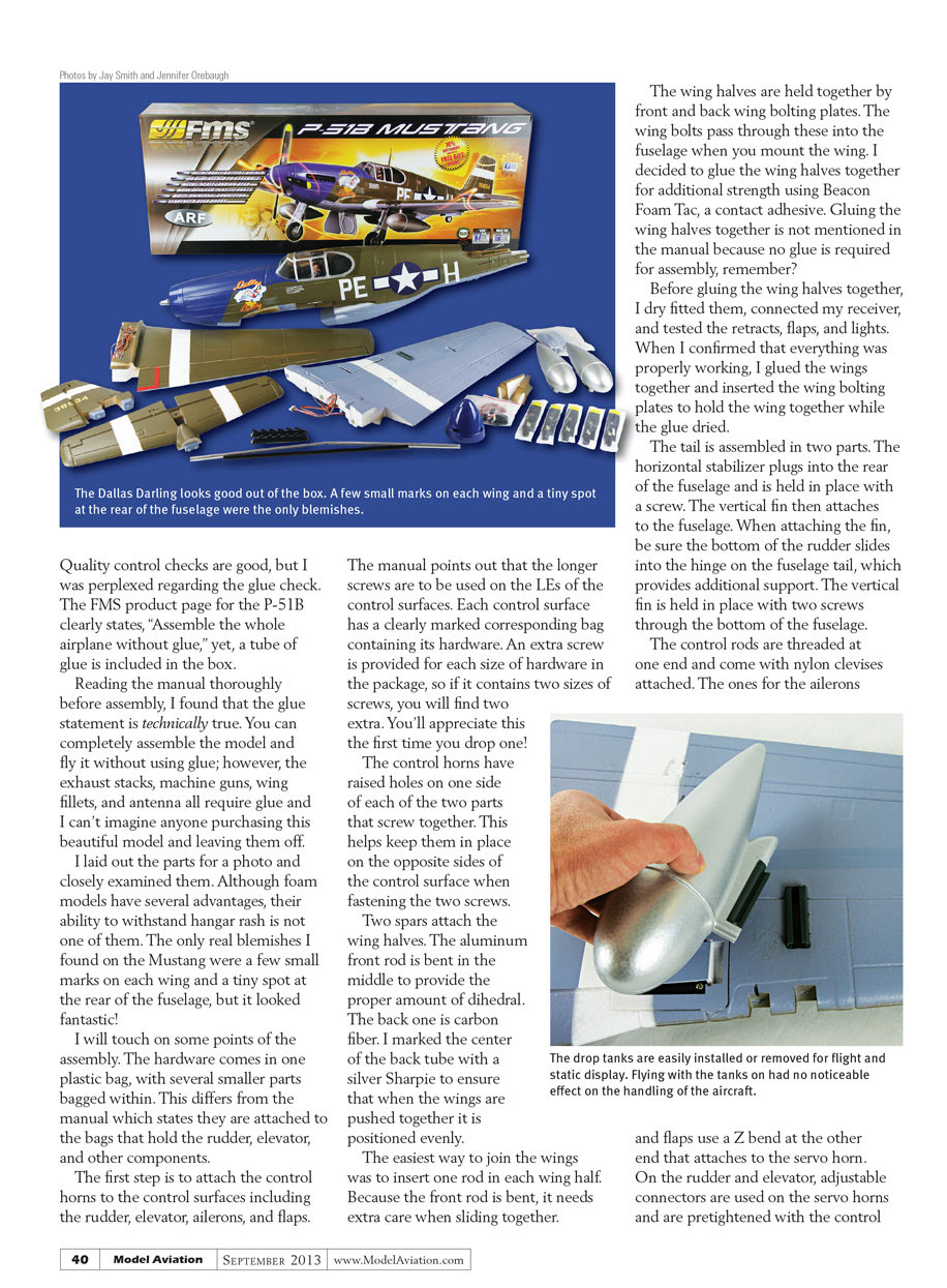
I don't normally comment on the box or the packaging, but this time I will make an exception. The model arrived from Motion RC, a new company that stocks FMS models, parts, and accessories. It came double boxed and the inner box caught my attention. Not only was it well illustrated with excellent photos of both versions of the P-51B, it proudly stated that 70% of customers would receive a free gift.
I wondered if I would be lucky and what kind of gift I might receive. I was lucky and my gift was another set of propeller blades!
I found a quality-control sheet with the following checked off: servo response check; motor and ESC check; power-on check; glue check; appearance check; and accessory package check. Quality control checks are good, but I was perplexed regarding the glue check. The FMS product page for the P-51B clearly states, "Assemble the whole airplane without glue," yet, a tube of glue is included in the box.
Reading the manual thoroughly before assembly, I found that the glue statement is technically true. You can completely assemble the model and fly it without using glue; however, the exhaust stacks, machine guns, wing fillets, and antenna all require glue and I can't imagine anyone purchasing this beautiful model and leaving them off.
I laid out the parts for a photo and closely examined them. Although foam models have several advantages, their ability to withstand hangar rash is not one of them. The only real blemishes I found on the Mustang were a few small marks on each wing and a tiny spot at the rear of the fuselage, but it looked fantastic!
I will touch on some points of the assembly. The hardware comes in one plastic bag, with several smaller parts bagged within. This differs from the manual which states they are attached to the bags that hold the rudder, elevator, and other components.
The first step is to attach the control horns to the control surfaces including the rudder, elevator, ailerons, and flaps.
The manual points out that the longer screws are to be used on the LEs of the control surfaces. Each control surface has a clearly marked corresponding bag containing its hardware. An extra screw is provided for each size of hardware in the package, so if it contains two sizes of screws, you will find two extra. You'll appreciate this the first time you drop one!
The control horns have raised holes on one side of each of the two parts that screw together. This helps keep them in place on the opposite sides of the control surface when fastening the two screws.
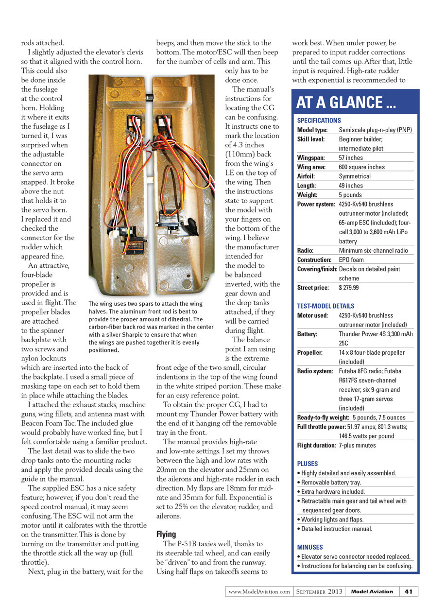
Two spars attach the wing halves. The aluminum front rod is bent in the middle to provide the proper amount of dihedral. The back one is carbon fiber. I marked the center of the back tube with a silver Sharpie to ensure that when the wings are pushed together it is positioned evenly.
The easiest way to join the wings was to insert one rod in each wing half. Because the front rod is bent, it needs extra care when sliding together.
The wing halves are held together by front and back wing bolting plates. The wing bolts pass through these into the fuselage when you mount the wing. I decided to glue the wing halves together for additional strength using Beacon Foam Tac, a contact adhesive. Gluing the wing halves together is not mentioned in the manual because no glue is required for assembly, remember?
Before gluing the wing halves together, I dry fitted them, connected my receiver, and tested the retracts, flaps, and lights. When I confirmed that everything was properly working, I glued the wings together and inserted the wing bolting plates to hold the wing together while the glue dried.
The tail is assembled in two parts. The horizontal stabilizer plugs into the rear of the fuselage and is held in place with a screw. The vertical fin then attaches to the fuselage. When attaching the fin, be sure the bottom of the rudder slides into the hinge on the fuselage tail, which provides additional support. The vertical fin is held in place with two screws through the bottom of the fuselage.
The control rods are threaded at one end and come with nylon clevises attached. The ones for the ailerons and flaps use a Z bend at the other end that attaches to the servo horn. On the rudder and elevator, adjustable connectors are used on the servo horns and are pretightened with the control rods attached.
I slightly adjusted the elevator’s clevis so that it aligned with the control horn. This could also be done inside the fuselage at the control horn. Holding it where it exits the fuselage as I turned it, I was surprised when the adjustable connector on the servo arm snapped. It broke above the nut that holds it to the servo horn. I replaced it and checked the connector for the rudder which appeared fine.
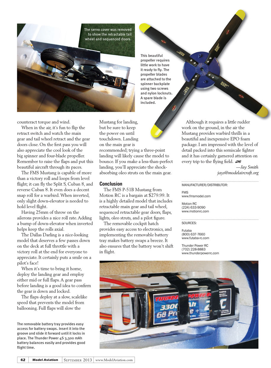
An attractive, four-blade propeller is provided and is used in flight. The propeller blades are attached to the spinner backplate with two screws and nylon locknuts which are inserted into the back of the backplate. I used a small piece of masking tape on each set to hold them in place while attaching the blades.
I attached the exhaust stacks, machine guns, wing fillets, and antenna mast with Beacon Foam Tac. The included glue would probably have worked fine, but I felt comfortable using a familiar product.
The last detail was to slide the two drop tanks onto the mounting racks and apply the provided decals using the guide in the manual.
The supplied ESC has a nice safety feature; however, if you don’t read the speed control manual, it may seem confusing. The ESC will arm the motor until it calibrates with the throttle on the transmitter. This is done by turning on the transmitter and putting the throttle stick all the way up (full throttle).
Next, plug in the battery, wait for the beeps, and then move the stick to the bottom. The motor/ESC will then beep for the number of cells and arm. This only has to be done once.
The manual’s instructions for locating the CG can be confusing. It instructs one to mark the location of 4.3 inches (110mm) back from the wing’s LE on the top of the wing. Then the instructions state to support the model with your fingers on the bottom of the wing. I believe the manufacturer intended for the model to be balanced inverted, with the gear down and the drop tanks attached, if they will be carried during flight.
The balance point I am using is the extreme front edge of the two small, circular indentions in the top of the wing found in the white striped portion. These make for an easy reference point.
To obtain the proper CG, I had to mount my Thunder Power battery with the end of it hanging off the removable tray in the front.
The manual provides high-rate and low-rate settings. I set my throws between the high and low rates with 20mm on the elevator and 25mm on the ailerons and high-rate rudder in each direction. My flaps are 18mm for mid-rate and 35mm for full. Exponential is set to 25% on the elevator, rudder, and ailerons.
Flying
The P-51B taxies well, thanks to its steerable tail wheel, and can easily be “driven” to and from the runway. Using half flaps on takeoffs seems to work best. When under power, be prepared to input rudder corrections until the tail comes up. After that, little input is required. High-rate rudder with exponential is recommended; trying a three-point landing will likely cause the model to bounce. If you make a less-than-perfect landing, you'll appreciate the shock-absorbing oleo struts on the main gear.
Conclusion
The FMS P-51B Mustang from Motion RC is a bargain at $279.99. It is a highly detailed model that includes retractable main gear and tail wheel, sequenced retractable gear doors, flaps, lights, oleo struts, and a pilot figure.
The removable cockpit hatch provides easy access to electronics, and implementing the removable battery tray makes battery swaps a breeze. It also ensures that the battery won't shift in flight.
Although it requires a little rudder work on the ground, in the air the Mustang provides warbird thrills in a beautiful and inexpensive EPO foam package. I am impressed with the level of detail packed into this semiscale fighter and it has certainly garnered attention on every trip to the flying field.
— Jay Smith [email protected]
MANUFACTURER/DISTRIBUTOR:
- FMS
- Motion RC
(224) 633-9090 www.motionrc.com
SOURCES:
- Futaba
(800) 637-7660 www.futaba-rc.com
- Thunder Power RC
(702) 228-8883 www.thunderpowerrc.com
Transcribed from original scans by AI. Minor OCR errors may remain.

