

FREE FLIGHT DURATION
Louis Joyner, 6 Saturday Rd., Mt. Pleasant SC 29464
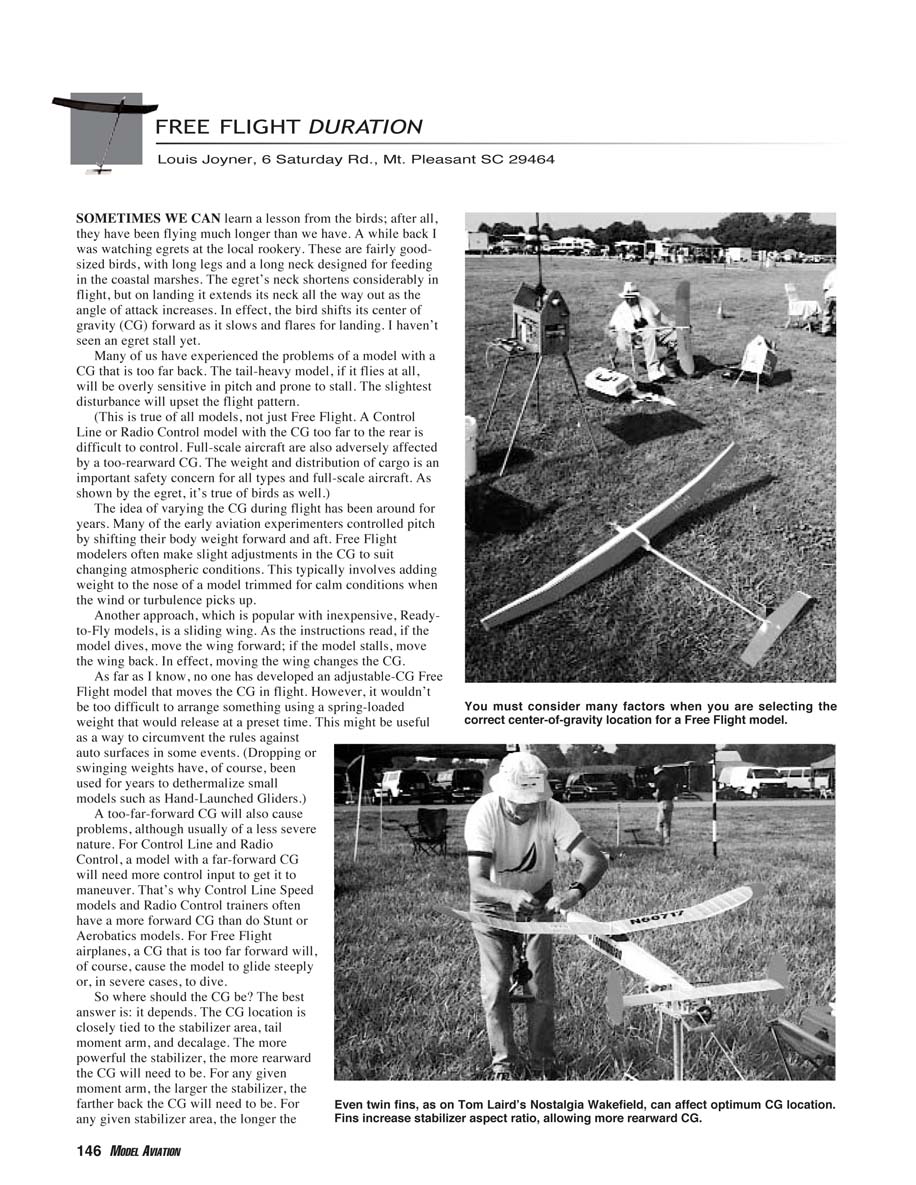
SOMETIMES WE CAN learn a lesson from the birds; after all, they have been flying much longer than we have. A while back I was watching egrets at the local rookery. These are fairly good-sized birds, with long legs and a long neck designed for feeding in the coastal marshes. The egret's neck shortens considerably in flight, but on landing it extends its neck all the way out as the angle of attack increases. In effect, the bird shifts its center of gravity (CG) forward as it slows and flares for landing. I haven't seen an egret stall yet.
Many of us have experienced the problems of a model with a CG that is too far back. The tail-heavy model, if it flies at all, will be overly sensitive in pitch and prone to stall. The slightest disturbance will upset the flight pattern.
(This is true of all models, not just Free Flight. A Control Line or Radio Control model with the CG too far to the rear is difficult to control. Full-scale aircraft are also adversely affected by a too-rearward CG. The weight and distribution of cargo is an important safety concern for all types and full-scale aircraft. As shown by the egret, it's true of birds as well.)
The idea of varying the CG during flight has been around for years. Many of the early aviation experimenters controlled pitch by shifting their body weight forward and aft. Free Flight modelers often make slight adjustments in the CG to suit changing atmospheric conditions. This typically involves adding weight to the nose of a model trimmed for calm conditions when the wind or turbulence picks up.
Another approach, which is popular with inexpensive ready-to-fly models, is a sliding wing. As the instructions read: if the model dives, move the wing forward; if the model stalls, move the wing back. In effect, moving the wing changes the CG.
As far as I know, no one has developed an adjustable-CG Free Flight model that moves the CG in flight. However, it wouldn't be too difficult to arrange something using a spring-loaded weight that would release at a preset time. This might be useful as a way to circumvent the rules against auto surfaces in some events. (Dropping or swinging weights have, of course, been used for years to dethermalize small models such as hand-launched gliders.)
A too-far-forward CG will also cause problems, although usually of a less severe nature. For Control Line and Radio Control, a model with a far-forward CG will need more control input to get it to maneuver. That's why Control Line Speed models and Radio Control trainers often have a more forward CG than do Stunt or Aerobatics models. For Free Flight airplanes, a CG that is too far forward will, of course, cause the model to glide steeply or, in severe cases, to dive.
Where should the CG be?
So where should the CG be? The best answer is: it depends. The CG location is closely tied to the stabilizer area, tail moment arm, and decalage. General relationships include:
- The more powerful the stabilizer, the more rearward the CG will need to be.
- For any given moment arm, the larger the stabilizer, the farther back the CG will need to be.
- For any given stabilizer area, the longer the moment arm, the farther back the CG will need to be.
Decalage, also called longitudinal dihedral, is the difference between wing and stabilizer incidence. This is the absolute difference independent of the fuselage reference line. For example, a model with the wing set at 0° relative to the fuselage and the stabilizer set at −3° will have the same decalage as a model with the wing at +3° and the stabilizer at 0°. As a rule, the larger the decalage, the farther forward the CG can be.
Many power models from the 1950s used little decalage in an effort to reduce the model's tendency to loop under power (0–0 decalage and 100% CG were not unheard of). When everything worked, these models would fly great, but often the slightest upset would result in a spectacular straight-up and straight-down power pattern. The introduction of downthrust allowed the CG to be moved slightly forward and the decalage increased, resulting in a safer, more consistent climb, recovery, and glide.
The development of timer-controlled auto surfaces allowed the climb and glide segments of the flight to be isolated and dealt with separately. This has allowed Power models' CGs to move forward considerably, into the 50–55% range.
Contest rules during the 1930s and 1940s often imposed a minimum fuselage cross-section based on the model's overall length. The longer the model, the fatter the fuselage. Since a fat fuselage caused extra drag, designers kept the fuselage as short as possible and used a large stabilizer. With the elimination of the cross-section rule based on fuselage length, models got longer and stabilizers got smaller.
A typical Wakefield rubber model of the late 1930s measured approximately 36 inches in overall length with a 33% stabilizer. Today's Wakefields are well more than a foot longer and have a stabilizer area of 20% of the wing or less. This small stabilizer, combined with an auto stabilizer to control the power burst, allows a more forward CG, typically near 55%.
Calculating the optimum CG
The CG's optimum location can be calculated. The basic idea is to find the neutral point (NP) and then locate the CG forward of the NP. The amount that the CG is located in front of the NP is called the stability margin (SM). Increasing the SM improves stall recovery but can decrease the model's still-air performance.
The NP's location depends on:
- wing area,
- stabilizer area,
- tail moment arm, and
- average wing chord.
Some other factors also enter in, including wing and stabilizer airfoils, stabilizer aspect ratio, and location of the wing relative to the fuselage centerline.
Perhaps the most useful method of calculating the CG for all types of Free Flight models is a formula that French modeler Rene Jossien developed some years back. It takes into account the type of model, weather conditions, airfoils, and several other factors. It's too long to present here, but it has been widely published through the years. You can find the formula on the Internet at: www.acscl.net/~regiaero/centeroftg.html. Using his formula should get you within 1% or 2% of the optimum CG — much closer than the usual guess.
Tandem P-30
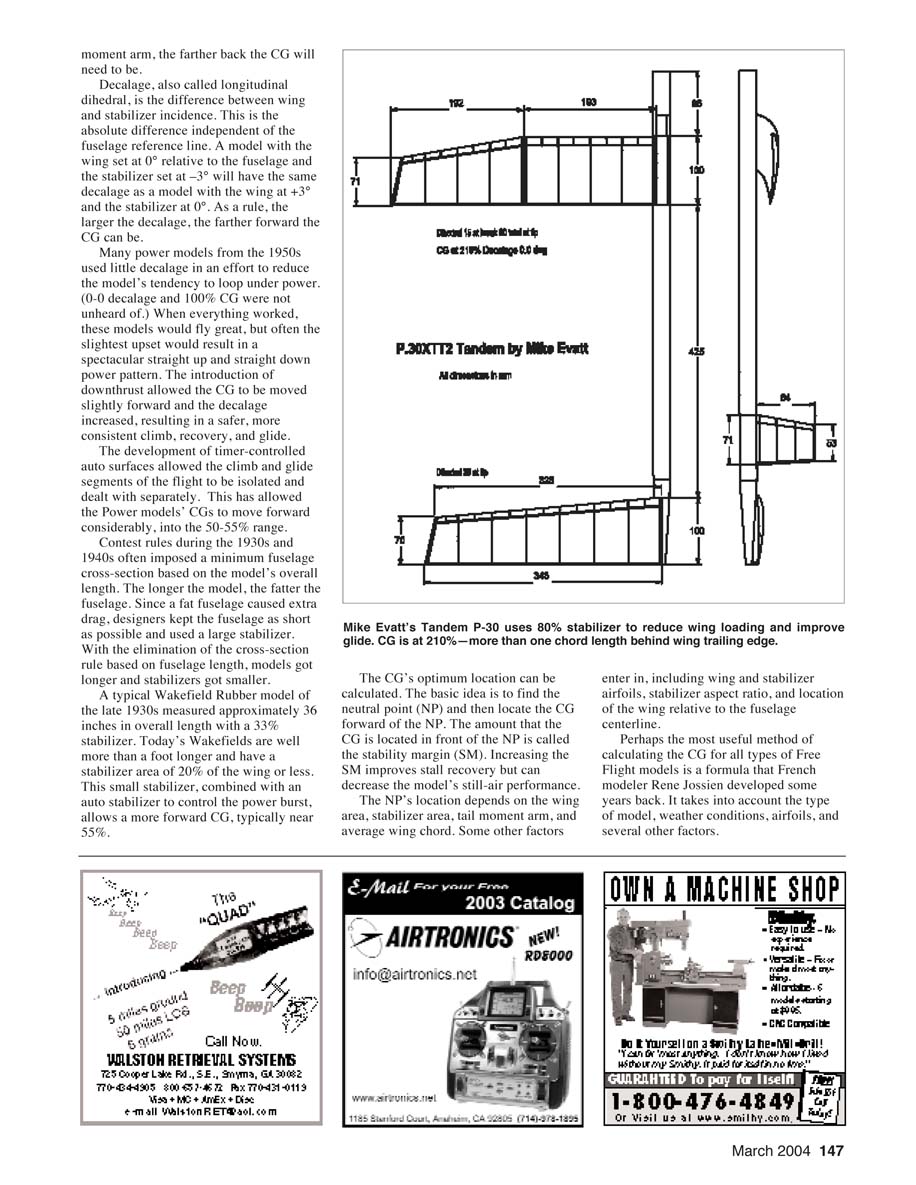
Some of today's events such as P-30 place a maximum overall length and maximum wingspan on the models. Since there is no restriction on the wing area or the total area, modelers are free to try a variety of approaches. This has led to models with extremely wide wing chords, to pack as much area as possible into the allotted 30-inch span. However, these low-aspect-ratio wings suffer from increased drag.
Mike Evatt in Great Britain is exploring another interesting approach: the tandem. Mike's idea is to increase the total area to reduce wing loading and improve the glide without resorting to a wide wing chord. His tandem designs use a stabilizer that is only slightly less than the wing area (80–85%) with a CG between 180% and 210% of the wing chord. Yes, the model balances one chord length behind the trailing edge!
For comparison, his conventional P-30 design uses a 35% stabilizer and a 60% CG. Based on glide tests, the tandem configuration offers a significant increase in performance, with a higher climb and a longer glide. Mike's predictions are a total duration increase of just more than 11% compared to his conventional P-30 with geared motor.
For more about Mike's P-30 experiments, order the 2003 Symposium report of the National Free Flight Society (NFFS). Copies are $25 for NFFS members and $30 for nonmembers. Postage is $4 extra. Order from:
- NFFS Publications, c/o Jim Zolbe, 4801 Braddock Ct., Lincoln NE 68516
- Email: [email protected]
For information about joining the NFFS, visit the website: www.freeflight.org or contact the new membership officer, J.P. Kish. Please send membership applications to:
- NFFS Membership Office, 22 Pine St., Homosassa FL 34446
The dues are $25 per year or $48 for two years. For more information, contact J.P. at [email protected].
MA
Transcribed from original scans by AI. Minor OCR errors may remain.

