
FREE FLIGHT DURATION
Louis Joyner, 6 Saturday Rd., Mt. Pleasant SC 29464
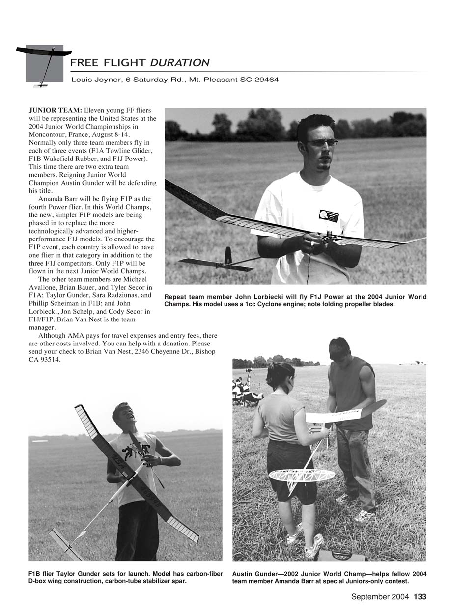
JUNIOR TEAM: Eleven young free-flight fliers will be representing the United States at the 2004 Junior World Championships in Moncontour, France, August 8–14. Normally only three team members fly in each of three events (F1A Towline Glider, F1B Wakefield Rubber, and F1J Power). This time there are two extra team members. Reigning Junior World Champion Austin Gunder will be defending his title.
Amanda Barr will be flying F1P as the fourth power flier. In this World Champs the new, simpler F1P models are being phased in to replace the more technologically advanced and higher-performance F1J models. To encourage the F1P event, each country is allowed to have one flier in that category in addition to the three F1J competitors. Only F1P will be flown in the next Junior World Champs.
Team members:
- F1A: Michael Avallone, Brian Bauer, Tyler Secor
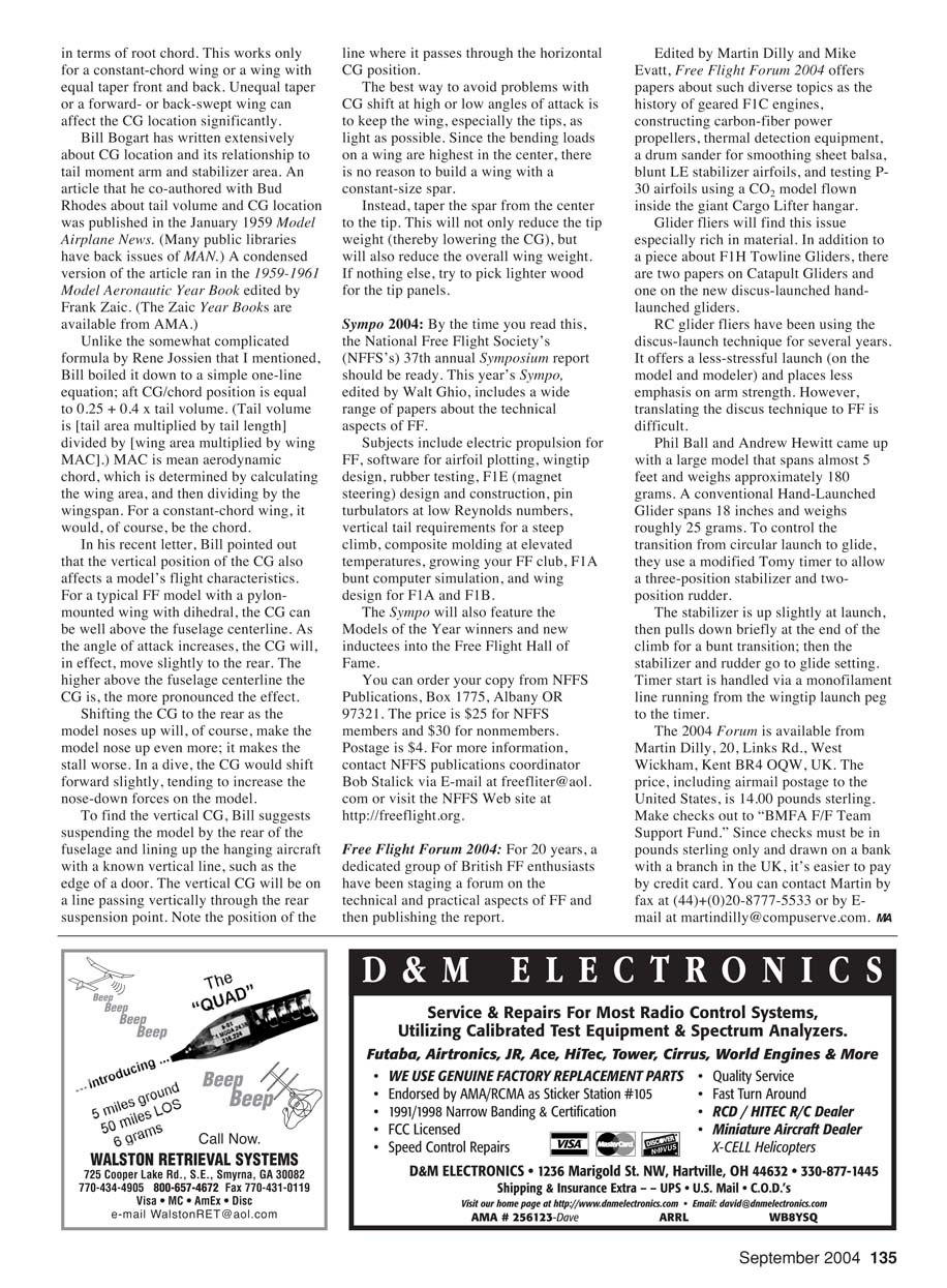
- F1B: Taylor Gunder, Sara Radziunas, Phillip Scheiman
- F1J/F1P: John Lorbiecki, Jon Schelp, Cody Secor
- F1P (additional power flier): Amanda Barr
Brian Van Nest is the team manager.
Although AMA pays for travel expenses and entry fees, there are other costs involved. You can help with a donation. Please send your check to Brian Van Nest, 2346 Cheyenne Dr., Bishop CA 93514.
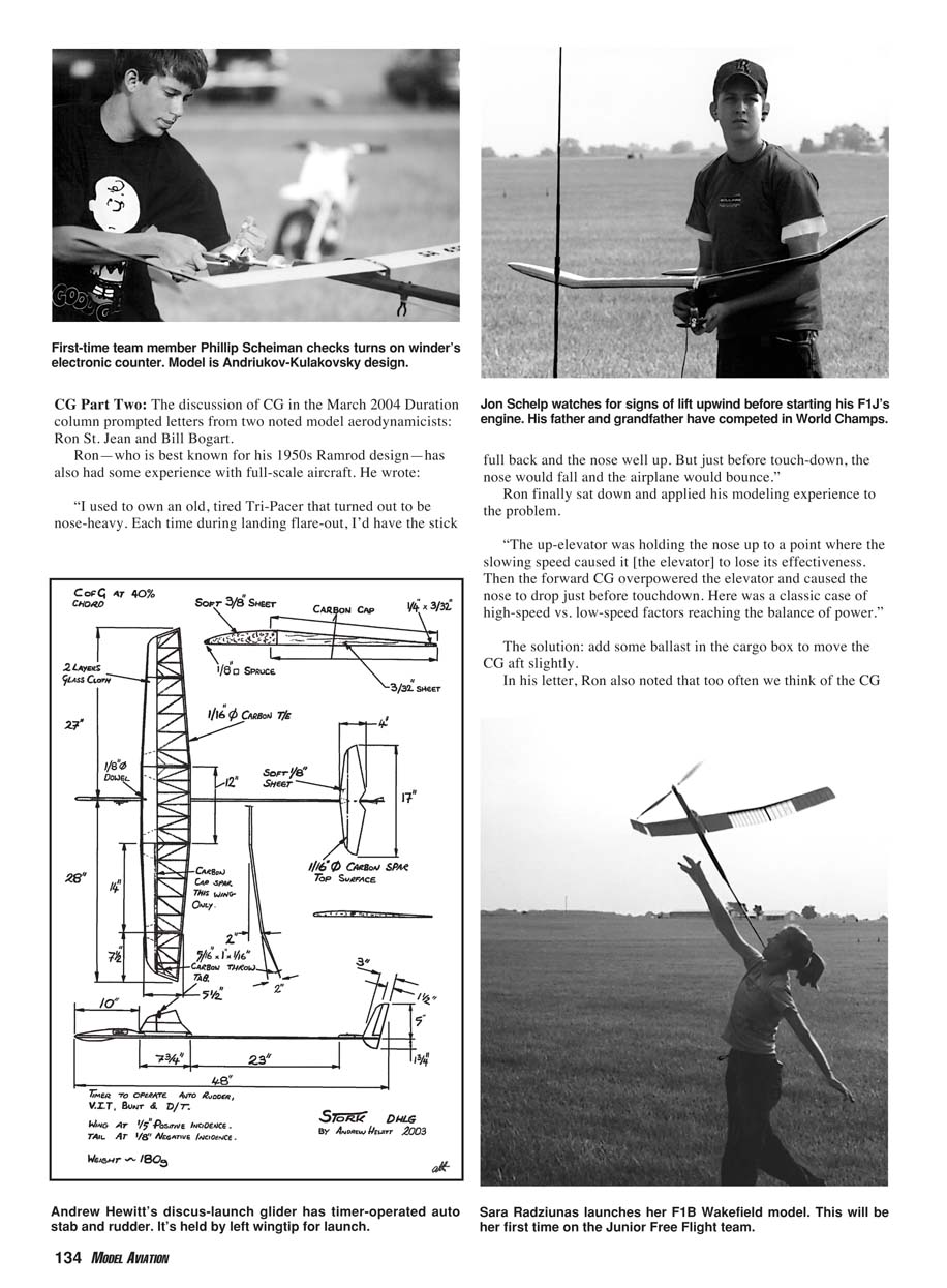
CG Part Two
The discussion of CG in the March 2004 Duration column prompted letters from two noted model aerodynamicists: Ron St. Jean and Bill Bogart.
Ron—best known for his 1950s Ramrod design—has also had some experience with full-scale aircraft. He wrote:
“I used to own an old, tired Tri-Pacer that turned out to be nose-heavy. Each time during landing flare-out, I’d have the stick full back and the nose well up. But just before touchdown, the nose would fall and the airplane would bounce.”
Ron finally sat down and applied his modeling experience to the problem.
“The up-elevator was holding the nose up to a point where the slowing speed caused it [the elevator] to lose its effectiveness. Then the forward CG overpowered the elevator and caused the nose to drop just before touchdown. Here was a classic case of high-speed vs. low-speed factors reaching the balance of power.”
The solution: add some ballast in the cargo box to move the CG aft slightly.
In his letter, Ron also noted that too often we think of the CG in terms of root chord. This works only for a constant-chord wing or a wing with equal taper front and back. Unequal taper or a forward- or back-swept wing can affect the CG location significantly.
Bill Bogart has written extensively about CG location and its relationship to tail moment arm and stabilizer area. An article he co-authored with Bud Rhodes about tail volume and CG location was published in the January 1959 Model Airplane News. A condensed version ran in the 1959–1961 Model Aeronautic Year Book edited by Frank Zaic. Unlike the somewhat complicated formula by Rene Josien that I mentioned, Bill boiled it down to a simple one-line equation: aft CG/chord position = 0.25 + 0.4 × tail volume.
Tail volume = (tail area × tail length) ÷ (wing area × wing MAC). MAC is mean aerodynamic chord, which is determined by calculating the wing area and then dividing by the wingspan. For a constant-chord wing, MAC is simply the chord.
In his recent letter, Bill pointed out that the vertical position of the CG also affects a model's flight characteristics. For a typical free-flight model with a pylon-mounted wing with dihedral, the CG can be well above the fuselage centerline. As the angle of attack increases, the CG will, in effect, move slightly to the rear. The higher above the fuselage centerline the CG is, the more pronounced the effect.
Shifting the CG to the rear as the model noses up will, of course, make the model nose up even more; it makes the stall worse. In a dive, the CG would shift forward slightly, tending to increase the nose-down forces on the model.
To find the vertical CG, Bill suggests suspending the model by the rear of the fuselage and lining up the hanging aircraft with a known vertical line, such as the edge of a door. The vertical CG will be on a line passing vertically through the rear suspension point. Note the position of that line where it passes through the horizontal CG position.
The best way to avoid problems with CG shift at high or low angles of attack is to keep the wing, especially the tips, as light as possible. Since the bending loads on a wing are highest in the center, there is no reason to build a wing with a constant-size spar. Instead, taper the spar from the center to the tip. This will reduce tip weight (thereby lowering the CG) and will also reduce overall wing weight. If nothing else, try to pick lighter wood for the tip panels.
Sympo 2004
By the time you read this, the National Free Flight Society's (NFFS) 37th annual Symposium report should be ready. This year's Sympo, edited by Walt Ghio, includes a wide range of papers about the technical aspects of free flight.
Subjects include:
- Electric propulsion for free flight
- Software for airfoil plotting
- Wingtip design
- Rubber testing
- F1E (magnet steering) design and construction
- Pin turbulators at low Reynolds numbers
- Vertical tail requirements for a steep climb
- Composite molding at elevated temperatures
- Growing your free-flight club
- F1A bungee computer simulation
- Wing design for F1A and F1B
The Sympo also features the Models of the Year winners and new inductees into the Free Flight Hall of Fame.
You can order your copy from NFFS Publications, Box 1775, Albany OR 97321. The price is $25 for NFFS members and $30 for nonmembers. Postage is $4. For more information, contact NFFS publications coordinator Bob Stalcik via e-mail at [email protected] or visit the NFFS website at http://freeflight.org.
Free Flight Forum 2004
For 20 years, a dedicated group of British free-flight enthusiasts have been staging a forum on the technical and practical aspects of free flight and publishing the report.
Edited by Martin Dilly and Mike Evatt, Free Flight Forum 2004 offers papers about diverse topics such as:
- The history of geared F1C engines
- Constructing carbon-fiber power propellers
- Thermal detection equipment
- A drum sander for smoothing sheet balsa
- Blunt leading-edge stabilizer airfoils
- Testing P-30 airfoils using a CO2 model flown inside the giant CargoLifter hangar
Glider fliers will find this issue especially rich. In addition to a piece about F1H Towline Gliders, there are two papers on catapult gliders and one on the new discus-launched hand-launched gliders.
RC glider fliers have been using the discus-launch technique for several years. It offers a less stressful launch (on both model and modeller) and places less emphasis on arm strength. However, translating the discus technique to free flight is difficult.
Phil Ball and Andrew Hewitt developed a large model that spans almost 5 feet and weighs approximately 180 grams. A conventional hand-launched glider spans 18 inches and weighs roughly 25 grams. To control the transition from circular launch to glide, they use a modified Tomy timer to allow a three-position stabilizer and two-position rudder.
The stabilizer is slightly up at launch, then pulls down briefly at the end of the climb for a burst transition; then the stabilizer and rudder go to the glide setting. Timer start is handled via a monofilament line running from the wingtip launching peg to the timer.
The 2004 Forum is available from Martin Dilly, 20 Links Rd., West Wickham, Kent BR4 0QW, UK. The price, including airmail postage to the United States, is 14.00 pounds sterling. Make checks out to "BMFA FF Team Support Fund." Since checks must be in pounds sterling only and drawn on a bank with a branch in the UK, it's easier to pay by credit card. You can contact Martin by fax at +44 (0)20 8777 5533 or by e-mail at [email protected].
Transcribed from original scans by AI. Minor OCR errors may remain.

