
FREE FLIGHT DURATION
Louis Joyner 6 Saturday Rd., Mt. Pleasant SC 29464
Going Around in Circles
Free-flight (FF) models—both indoor and outdoor types—normally fly in circles. For indoor models, a circular flight path is necessary to avoid hitting the walls. For outdoor models, circling helps keep the airplane on the field longer and allows it to better take advantage of thermals.
Setting up a FF model for circular flight is also easier than trying to trim an aircraft to fly perfectly straight. The only FF models designed for a straight flight path are speed airplanes and F1E slope-soaring gliders. For rubber-powered speed models, speed is measured between two lines, so a straight path minimizes the distance flown; trimming such a model requires accurate construction and careful balancing of motor torque. For F1E, a magnet steering device is used to hold the flight on a predetermined compass heading to position the model relative to the slope current; a timer then disengages the magnet-controlled rudder and the glider circles for the remainder of the flight.
For most outdoor FF, models must be designed to circle. Circular flight allows FF aircraft to fly without control input by using a variety of speed-sensitive adjustments to achieve the desired circular flight path—one that's not too tight or too open. Some adjustments (rudder offset, decalage—incidence differential—and wing wash-in or washout) become more effective at higher speeds. Other adjustments (CG location, thrust offsets, and stabilizer tilt) become more effective at lower speeds.
A typical example is a rubber model with right thrust and left rudder offset. As the model speeds up—such as immediately after launch when the rubber motor has maximum power—the left rudder is more effective than the right thrust offset, and the model flies a relatively straighter path. As the model slows near the end of the motor run, the right thrust offset becomes more effective than the left rudder offset, and the model turns more tightly to the right.
Another common balancing method is crossed controls. Right rudder combined with wash-in on the right wing can create a left roll; both adjustments grow in effectiveness with increased speed. If the model begins to turn too tightly to the right, the left roll caused by wash-in on the right wing will balance the right rudder and help prevent a spiral dive.
On-the-ground control inputs for outdoor FF models are generally slight. Rudder and stabilizer adjustments are usually made with 1/64" plywood shims or fine screw adjustments. Sometimes a quarter-turn of an 0-80 screw will make a significant difference in performance.
Asymmetry
Since outdoor FF models fly in circles, must they be symmetrical? It depends on the desired glide-circle diameter. The tighter the glide turn, the more asymmetry might help.
Measuring glide-circle diameter directly is difficult, so the glide turn is often measured by the time to complete one circle. This is easy to check with a stopwatch: start when the model is seen directly from the side and stop when it appears again. From that time and an estimate of the model’s airspeed, you can calculate the glide circle’s circumference and diameter.
Example calculations:
- If a towline glider has an airspeed of 4.0 m/s (≈13 ft/s) and completes a 30-second glide circle, it covers 120 m. That gives a glide-circle diameter of approximately 38.0 m (≈125 ft).
- If the turn is opened to a 60-second glide circle at the same airspeed, the model covers 240 m and the diameter increases to approximately 76.0 m (≈250 ft).
Because the model is flying in a circle, the outer wingtip travels farther than the inboard wingtip. The tighter the glide circle and the longer the span, the greater the difference in tip speeds. For a large model this can be significant.
Example with a 2.5 m span (≈98 in):
- For a 30-second glide circle covering 120.0 m at the fuselage center: the outer tip must go roughly 7.2 m farther than the fuselage, and the inner tip goes roughly 8.5 m less than the fuselage. The outer tip therefore covers about 15.7 m more than the inner tip.
- Tip speeds in that case: outer tip ≈ 4.24 m/s, fuselage ≈ 4.00 m/s, inner tip ≈ 3.72 m/s. The difference between tip airspeeds is ≈ 0.5 m/s—significant.
- For a more open 60-second glide circle (fuselage covering 240.0 m): the outer tip covers 246.6 m and the inner tip 230.9 m. The distance difference between tips is still 15.7 m, but it takes twice as long to cover it. Tip airspeeds are: outer ≈ 4.11 m/s, fuselage ≈ 4.00 m/s, inner ≈ 3.85 m/s. The tip speed difference is ≈ 0.26 m/s, about half the difference of the tighter turn.
Different tip airspeeds imply different Reynolds numbers across the span. Assuming a tip chord of 100 mm (≈4 in), the difference in tip Reynolds numbers for the tighter glide turn is roughly 13%; for the more open glide turn it is roughly 6.5%.
(Quick Reynolds number estimate: chord in millimeters × velocity in m/s × 70.)
Why care about Reynolds numbers? Airfoils—especially undercambered, high-lift, low-speed sections often used in FF—behave differently at different Reynolds numbers. For a long-wing model flown in a tight glide circle, there may be a benefit to using slightly different tip airfoils on the inboard and outboard tips, or different turbulator sizes/positions. In marginal conditions (e.g., early-morning flyoffs) such optimizations can make a difference.
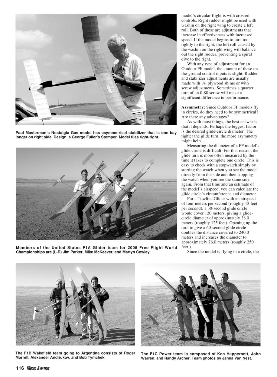
Another use of asymmetry is to make the inboard side of a wing or stabilizer larger to counterbalance torque under power or rudder-turning effects. The extra lift of the inner wing helps keep it up in a turn and can be less sensitive to speed changes than wash-in. A formula sometimes used to determine how much longer the inner wing should be is:
inner-wing-overspan ≈ (span^2) / (6 × radius of glide turn)
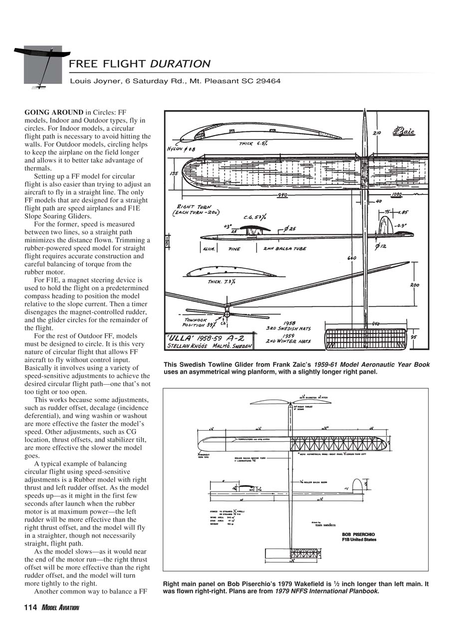
Historical references (Zaic Year Books) show examples of one-wing-longer-than-the-other approaches, especially on hand-launched gliders flown in very tight circles. However, a simpler and more common approach is to skew the wing slightly—approximately 1/64" on a 4" chord.
Personal note: In the early 1960s I experimented with asymmetrical dihedral on hand-launched gliders—one side V-dihedral and the other polyhedral. It looked odd but worked: flown right-right, the polyhedral side was more effective at keeping the inboard wing up in a thermal. Hand-launched and catapult gliders are inexpensive and quick to build, which makes such experimentation easy.
2005 United States Free Flight Team
After three intense days of flying in October, the U.S. team for the Free Flight World Championships is set.
F1A Towline Glider:
- Seven of the 30 fliers maxed out after 14 rounds. Five made the five- and seven-minute flyoffs.
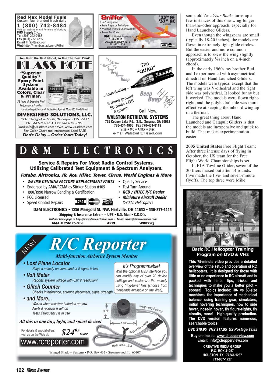
- Top three: Mike McKeever, Randy Weiler, Martyn Cowley.
- Randy Weiler decided to step down from the team because he and his wife are expecting their second child around the time of the World Championships in Argentina. That moved Jim Parker onto the team and made Ken Bauer the alternate.
F1B Wakefield:
- Nine of the 30 finalists maxed out.
- Alexander Andriukov topped the single flyoff with a flight of just over seven minutes. Although this is Alex’s first U.S.-team slot, he is no stranger to international competition—flying for Ukraine, he is a three-time World Champion, three-time World Cup winner, and four-time European Champion.
- Second: Roger Morrell (editor of the SCAT Electronic News website, www.aeromodel.com), eight seconds behind Alexander.
- Third: Bob Tymchek; alternate: Bob Piserchio.
F1C Power:
- Exactly half of the 24 finalists maxed out, with seven making the five-minute round.
- In a 10-minute early-morning flyoff, only two-time World Champion Randy Archer maxed out despite his engine blowing at the end of the run.
- Second: Ken Happersett (just two seconds shy of 600 s).
- Third team spot: John Warren; alternate: Dave Shirley.
Transcribed from original scans by AI. Minor OCR errors may remain.

