
Free Flight Duration
Louis Joyner [email protected]
2009 US FF World Champs team members
THE 2009 FF World Championships will take place this summer in Croatia. In October, the US Team Selection Finals took place in Lost Hills, California.
The team members:
- F1A Towline Glider: Ken Bauer, Lee Hines, Steve Spence
- F1B Wakefield Rubber: Alex Andriukov, Walt Ghio, Charlie Jones
- F1C Power: Don Chesson, Dick Mathis, Gil Morris
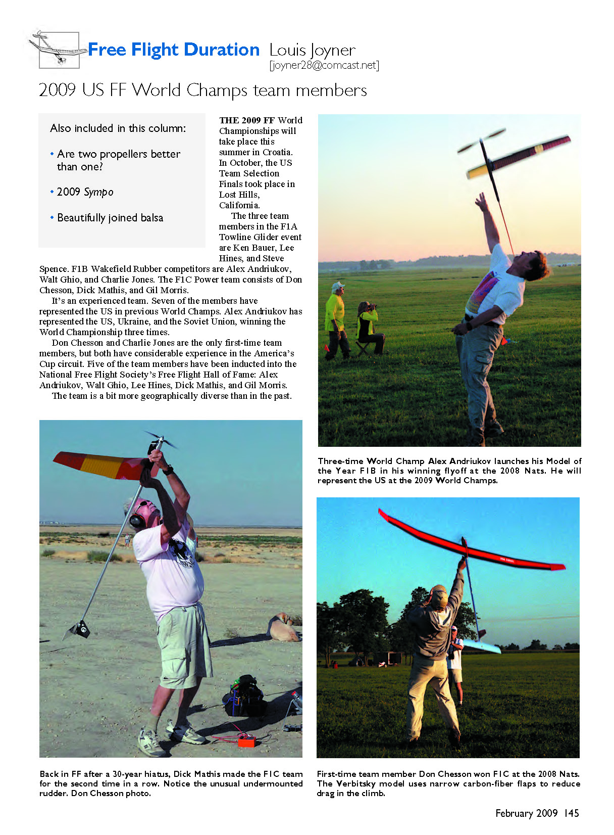
It's an experienced team. Seven members have represented the US in previous World Champs. Alex Andriukov has represented the US, Ukraine, and the Soviet Union, winning the World Championship three times.
Don Chesson and Charlie Jones are the only first-time team members, but both have considerable experience in the America's Cup circuit. Five team members are in the National Free Flight Society's Free Flight Hall of Fame: Alex Andriukov, Walt Ghio, Lee Hines, Dick Mathis, and Gil Morris.
Geographic distribution:
- California: Alex Andriukov, Ken Bauer, Walt Ghio, Lee Hines
- Ohio: Charlie Jones, Gil Morris
- Louisiana: Don Chesson, Dick Mathis (new hotbed of F1C)
- Texas: Steve Spence
Unlike many past finals, this one required no flyoffs. In F1A, Ken Bauer was the only pilot to max all rounds over the two days. In F1B, Walt Ghio and Charlie Jones maxed out. In F1C, the top three maxed to make the team. Don Chesson said, "I was prepared for and very much hoping for a big flyoff and confident that this would produce a fine team composed of any of the F1C participants. The overall quality of flying is so high, anybody can be in the winner's circle. The finals were tough, with very tricky air in the fifth through seventh rounds. I was very lucky to survive."
Are two propellers better than one?
One of the more interesting airplanes at the Team Selection Finals was Gil Morris's F1C Power model. As with many of the latest generation of F1C aircraft, it was a folder—but it's a folder with a difference. Gil calls it a "folder-flapper."
The wing and construction: the wing chord is 5 1/8 inches and the span is 110 inches. The foam core has a chord of only 4 inches and is covered with one piece of bias-cut carbon cloth so that the last inch of the chord is only two thicknesses of epoxy-impregnated carbon cloth. It's a sort of Jedelsky airfoil, and when the wing is folded the two trailing edges collapse to form a teardrop airfoil thinner than the sum of the two airfoils when free. The flaps drop down when the wing is opened to provide an undercamber in glide.
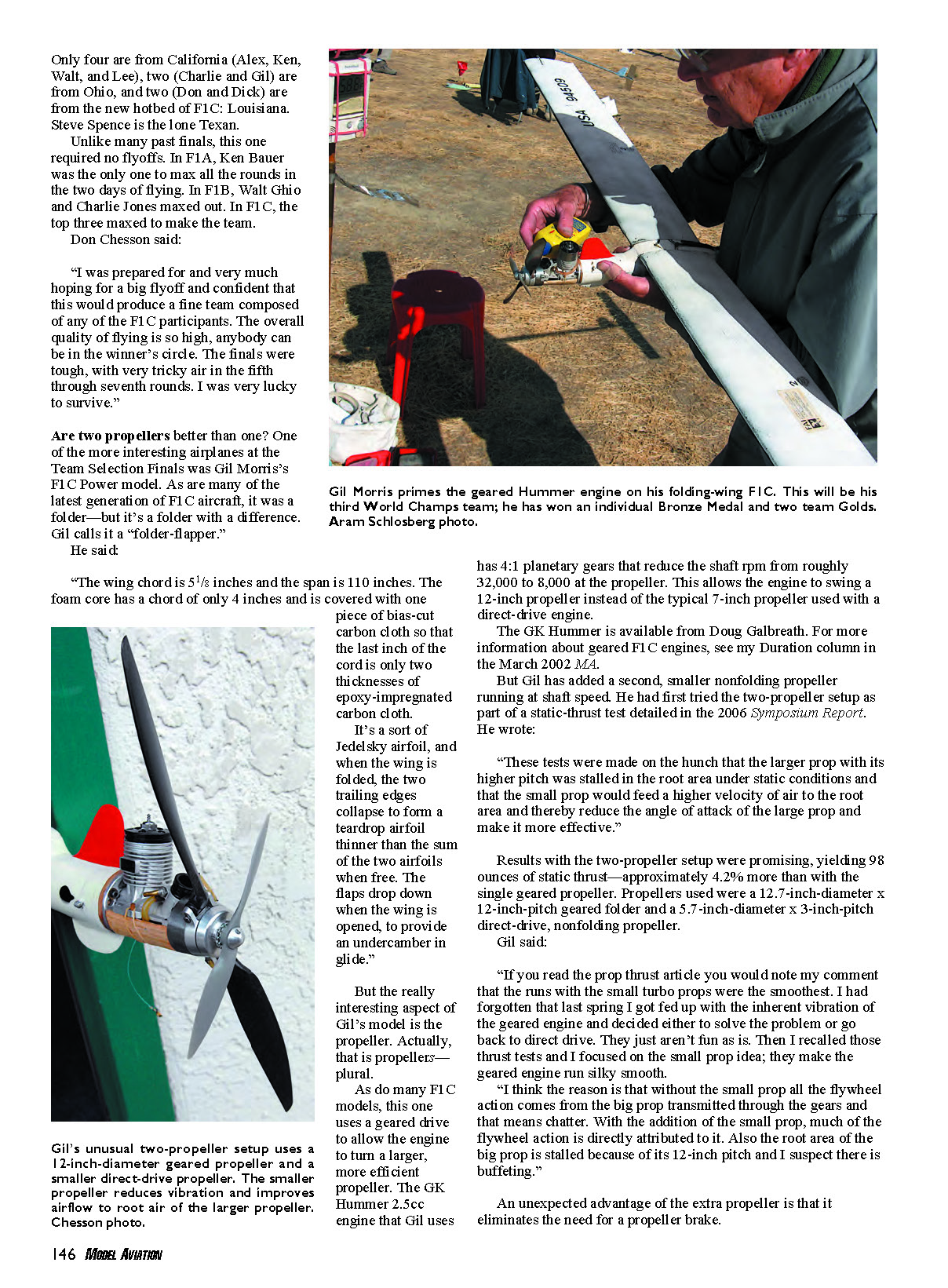
The propeller arrangement is the most interesting feature. Like many F1C models, this one uses a geared drive to allow the engine to turn a larger, more efficient propeller. The GK Hummer 2.5cc engine that Gil uses has 4:1 planetary gears that reduce the shaft rpm from roughly 32,000 to about 8,000 at the propeller. This allows the engine to swing a 12-inch propeller instead of the typical 7-inch propeller used with a direct-drive engine. The GK Hummer is available from Doug Galbreath. For more information about geared F1C engines, see the Duration column in the March 2002 MA.
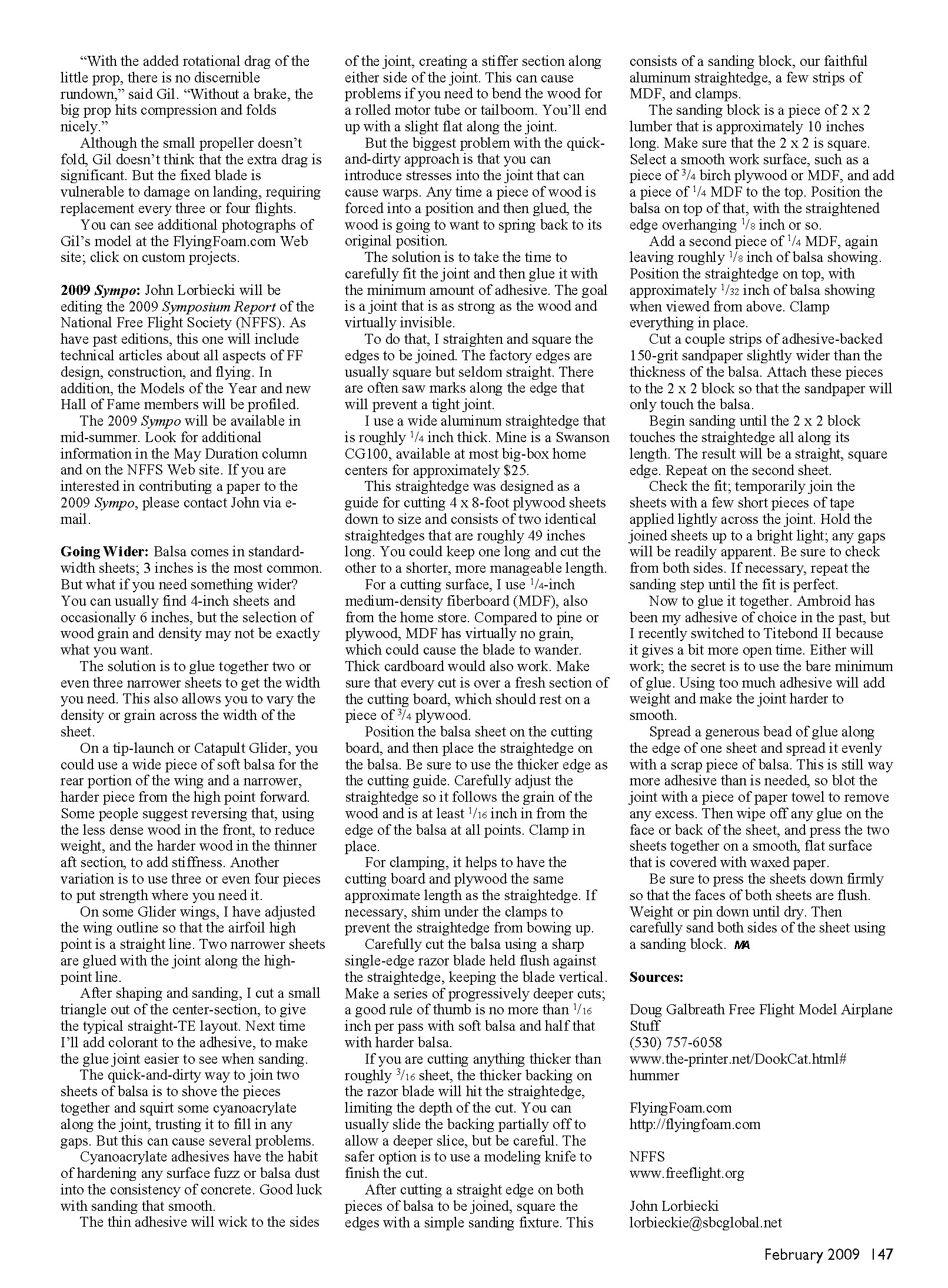
Gil has added a second, smaller nonfolding propeller running at shaft speed. He first tried the two-propeller setup as part of static-thrust tests detailed in the 2006 Symposium Report. He wrote: "These tests were made on the hunch that the larger prop was stalled in the root area under static conditions and that the small prop would feed a higher velocity of air to the root area and thereby reduce the angle of attack of the large prop and make it more effective."
Results from the two-propeller setup were promising, yielding 98 ounces of static thrust—approximately 4.2% more than with the single geared propeller. Propellers used were a 12.7-inch-diameter x 12-inch-pitch geared folder and a 5.7-inch-diameter x 3-inch-pitch direct-drive, nonfolding propeller.
Gil said:
"If you read the prop-thrust article you would note my comment that the runs with the small turbo props were the smoothest. I had gotten that last spring; I got fed up with the inherent vibration of the geared engine and decided either to solve the problem or go back to direct drive. They just aren't as fun as is. Then I recalled those thrust tests and I focused on the small prop idea; they make the geared engine run silky smooth.
I think the reason is that without the small prop all the flywheel action comes from the big prop transmitted through the gears and that means chatter. With the addition of the small prop, much of the flywheel action is directly attributed to it. Also the root area of the big prop is stalled because of its 12-inch pitch and I suspect there is some inefficiency."
An unexpected advantage of the extra propeller is that it eliminates the need for a propeller brake. "With the added rotational drag of the little prop, there is no discernible rundown," said Gil. "Without a brake, the big prop hits compression and folds nicely."
Although the small propeller doesn't fold, Gil doesn't think the extra drag is significant. However, the fixed blade is vulnerable to damage on landing and typically requires replacement every three or four flights.
You can see additional photographs of Gil's model at the FlyingFoam.com web site; click on Custom Projects.
2009 Sympo
John Lorbiecki will be editing the 2009 Symposium Report of the National Free Flight Society (NFFS). As with past editions, this one will include technical articles about all aspects of free flight design, construction, and flying. In addition, the Models of the Year and new Hall of Fame members will be profiled.
The 2009 Sympo will be available in mid-summer. Look for additional information in the May Duration column and on the NFFS web site. If you are interested in contributing a paper to the 2009 Sympo, please contact John via e-mail: [email protected].
Going Wider
Balsa comes in standard-width sheets; 3 inches is the most common. You can usually find 4-inch sheets and occasionally 6-inch sheets, but the selection of wood grain and density may not be exactly what you want.
A practical solution is to glue together two or three narrower sheets to achieve the width you need. This also allows you to vary density or grain across the width of the sheet.
Examples and layout tips:
- On a tip-launch or catapult glider, use a wide piece of soft balsa for the rear portion of the wing and a narrower, harder piece from the high point forward.
- Some builders reverse that: less dense wood in front to reduce weight and harder wood aft to add stiffness.
- Another variation is to use three or four pieces to put strength where you need it.
- On some glider wings, adjust the outline so the airfoil high point is a straight line; glue the two narrower sheets with the joint along that high-point line. After shaping and sanding, cut a small triangle out of the center-section to give a typical straight trailing-edge layout.
Avoid the quick-and-dirty method of simply forcing pieces together and wicking cyanoacrylate into the joint. Problems with that approach:
- Cyanoacrylate hardens surface fuzz and dust into a concrete-like consistency, making sanding difficult.
- Thin CA will wick to the sides of the joint, creating a stiff strip that can interfere with bending the wood for rolled motor tubes or tailbooms.
- Forcing wood into position before gluing can introduce stresses that later cause warps as the wood tries to spring back.
Aim for a joint as strong as the wood and virtually invisible. Recommended procedure:
- Prepare straight, square edges. Factory edges are often square but seldom straight—saw marks can prevent a tight joint. Use a long aluminum straightedge for cutting and squaring. A Swanson CG100 or similar is handy.
- Use a stable cutting surface such as 1/4-inch MDF over 3/4-inch plywood. Make sure each cut is over a fresh section of the cutting board. Cardboard also works.
- Position the balsa on the cutting board and clamp the straightedge at least 1/16 inch in from the edge, aligning with the grain. Use the thicker edge of the straightedge as the cutting guide and prevent the straightedge from bowing with proper clamping or shims.
- Cut with a sharp single-edge razor blade held flush to the straightedge, keeping the blade vertical. Make multiple shallow passes—no more than 1/16 inch per pass on soft balsa and half that on harder stock. For thicker sheets (over about 3/16 inch), a modeling knife may be safer to finish the cut.
- Square the edges with a sanding fixture: a 2 x 2 sanding block (~10 inches long), the aluminum straightedge, a few strips of MDF, and clamps. Place the balsa with the straightened edge overhanging about 1/8 inch, sandwich with 1/4-inch MDF strips, place the straightedge on top leaving ~1/32 inch of balsa exposed, and clamp. Attach 150-grit adhesive-backed sandpaper to the 2 x 2 so it only contacts the balsa, and sand until the block touches the straightedge along its length. Repeat for the second sheet.
- Check the fit by taping the two sheets lightly across the joint and holding up to a bright light to detect gaps. Repeat sanding until the fit is perfect.
- Glue with the minimum amount of adhesive. Ambroid has been a traditional choice; Titebond II offers more open time. Spread a thin even bead of glue along the edge, spread with scrap balsa, blot excess with paper towel, wipe faces clean, and press the sheets together on a flat surface covered with waxed paper. Ensure faces are flush, weight or pin down until dry, then carefully sand both sides smooth.
Using minimal glue reduces weight and makes the joint easier to finish.
Sources
- Doug Galbreath, Free Flight Model Airplane Stuff — (530) 757-6058 — www.the-printer.net/DookCat.html#hummer
- FlyingFoam.com — http://flyingfoam.com
- NFFS — www.freeflight.org
- John Lorbiecki — [email protected]
Transcribed from original scans by AI. Minor OCR errors may remain.

