
Free Flight Duration
Louis Joyner [[email protected]]
How many blades on a propeller is right for you?
FF models have traditionally used two-blade propellers. Some rubber-powered models from the 1930s through the 1950s used single blades, often to simplify construction (half the work) rather than for a performance advantage.
For gas models, manufacturers could machine a two-blade propeller from a relatively small piece of maple. When nylon and other plastic propellers came along some 50 years ago, the two-blade tradition was carried on.
For full-scale, piston-engine aircraft, three-, four-, and even five-blade propellers were developed to absorb the increasing power of engines without increasing diameter and compromising ground clearance. The Supermarine Spitfire prototype first flew in 1936 with a two-blade, fixed-pitch wooden propeller turned by a 990-horsepower engine. By the end of World War II, the Spitfire Mk XIV used a five-blade propeller turned by an engine that produced well more than twice the prototype’s horsepower.
In the last decade, there has been some revival of interest in single-blade propellers. Rudolf Harbinger’s Carbonator F1K model, detailed in the 2000 National Free Flight Society (NFFS) Symposium, uses a high-aspect-ratio, single-blade propeller. Rudolf’s balsa-and-carbon-fiber propeller has a diameter of roughly 10.25 inches. He claims an 8% increase in efficiency compared to a conventional two-blade propeller. A single blade’s efficiency advantage comes from being able to increase blade diameter using the same amount of power. For propeller diameter, bigger is generally better.
Rubber motors provide plenty of torque to slowly turn a big propeller. Outdoor rubber-model propellers typically average about 600 rpm; indoor-model propellers often turn one-tenth as quickly. Compared with gas-model propellers, rubber propellers are more efficient. Slowly moving a lot of air takes less energy than moving a small amount of air at high speeds.
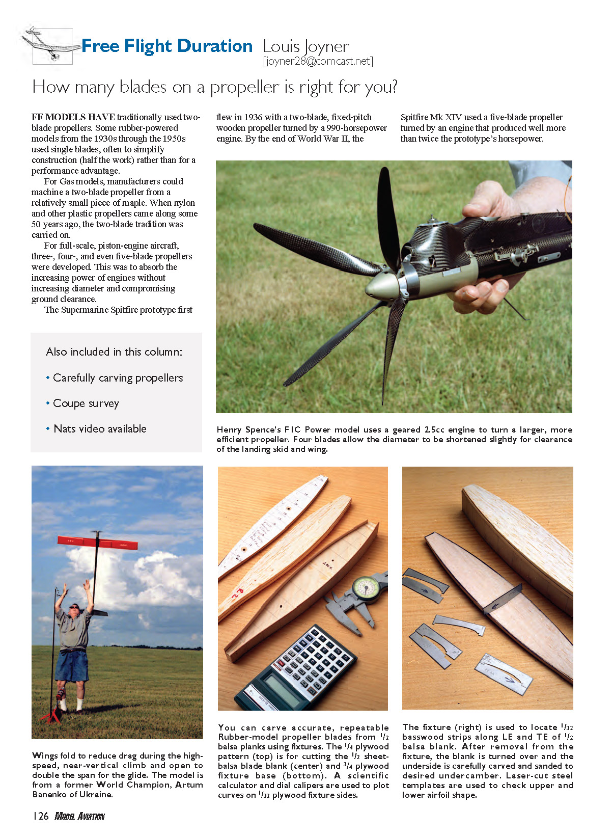
For gasoline-powered (gas) models, modern engines develop maximum power at extremely high revolutions but low torque. A 7-inch-diameter propeller turning 30,000 rpm affects a relatively small mass of air. Gearing down the engine allows it to turn a much larger-diameter (13–14 inch) propeller more slowly and more efficiently. The slower-turning propeller also avoids the problem of its blade tips approaching the speed of sound. But these bigger propellers can create clearance problems—not ground clearance, since the models are hand-launched vertically. Instead, the difficulty is with folding the big propeller for the glide.
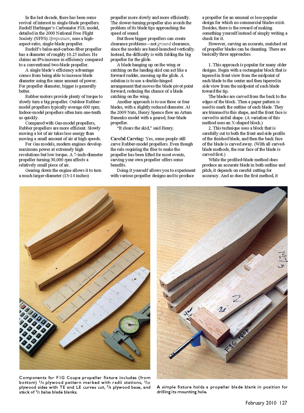
A blade hanging up on the wing or catching on the landing skid can act like a forward rudder, messing up the glide. A solution is to use a double-hinged arrangement that moves the blade pivot point forward, reducing the chance of a blade catching on the wing.
Another approach is to use three or four blades, with a slightly reduced diameter. At the 2009 Nats, Henry Spence flew an Artum Banenko model with a geared, four-blade propeller. "It clears the skid," said Henry.
Careful Carving
Yes, some people still carve rubber-model propellers. Even though the rule requiring the flier to make the propeller has been lifted for most events, carving your own propeller offers some benefits.
Doing it yourself allows you to experiment with various propeller designs and to produce a propeller for an unusual or less-popular design for which no commercial blades exist. Besides, there is the reward of making something yourself instead of simply writing a check for it.
However, carving an accurate, matched set of propeller blades can be daunting. There are basically three approaches.
- Begin with a rectangular block that is tapered in front view from the midpoint of each blade to the center and then tapered in side view from the midpoint of each blade toward the tip. The blades are carved from the back to the edges of the block. Then a paper pattern is used to mark the outline of each blade. They are trimmed to this shape, and the front face is carved to airfoil shape. (A variation of this method uses an X-shaped block.)
- This technique uses a block that is carefully cut to both the front and side profile of the finished blade, and then the back face of the blade is carved away. With all carved-blade methods, the rear face of the blade is carved first. While the profiled-blade method does produce an accurate blade in both outline and pitch, it depends on careful cutting for accuracy and, as does the first method, requires a large block of balsa.
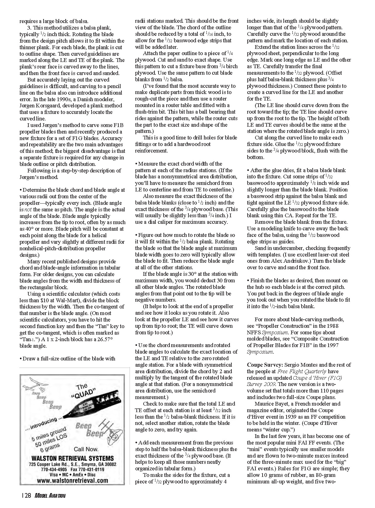
- This method utilizes a balsa plank, typically 1/2 inch thick. Rotating the blade from the design pitch allows it to fit within the thinner plank. For each blade, the plank is cut to outline shape. Then curved guidelines are marked along the leading edge (LE) and trailing edge (TE) of the plank. The plank’s rear face is carved away to the lines, and then the front face is carved and sanded. Accurately laying out the curved guidelines is difficult, and carving to a pencil line on the balsa also can introduce additional error.
In the late 1990s, Danish modeler Jørgen Korsgaard developed a plank method that uses a fixture to accurately locate the curved line. I used Jørgen’s method to carve some F1B propeller blades then and recently produced a new fixture for a set of F1G blades. Accuracy and repeatability are the two main advantages of this method; the biggest disadvantage is that a separate fixture is required for any change in blade outline or pitch distribution.
Following is a step-by-step description of Jørgen’s method.
- Determine the blade chord and blade angle at various radii out from the center of the propeller—typically every inch. (Blade angle is not the same as pitch. The angle is the actual angle of the blade relative to the plane of rotation. Blade angle typically increases from the tip to root, often by as much as 40° or more. Blade pitch will be constant at each point along the blade for a helical propeller and vary slightly at different radii for nonhelical-pitch-distribution designs.)
- Many recent published designs provide chord and blade-angle information in tabular form. For older designs, you can calculate blade angles from the width and thickness of the rectangular block. Using a scientific calculator, divide the block thickness by the width and take the arctangent to get the blade angle. (On most scientific calculators, the inverse tangent is marked "tan^-1" or "arctan".) A 1 x 2-inch block gives approximately a 26.57° blade angle.
- Draw a full-size outline of the blade with radii stations marked. This should be the front view of the blade. The chord of the outline should be reduced by a total of 1/16 inch to allow for the 1/32-inch basswood edge strips that will be added later.
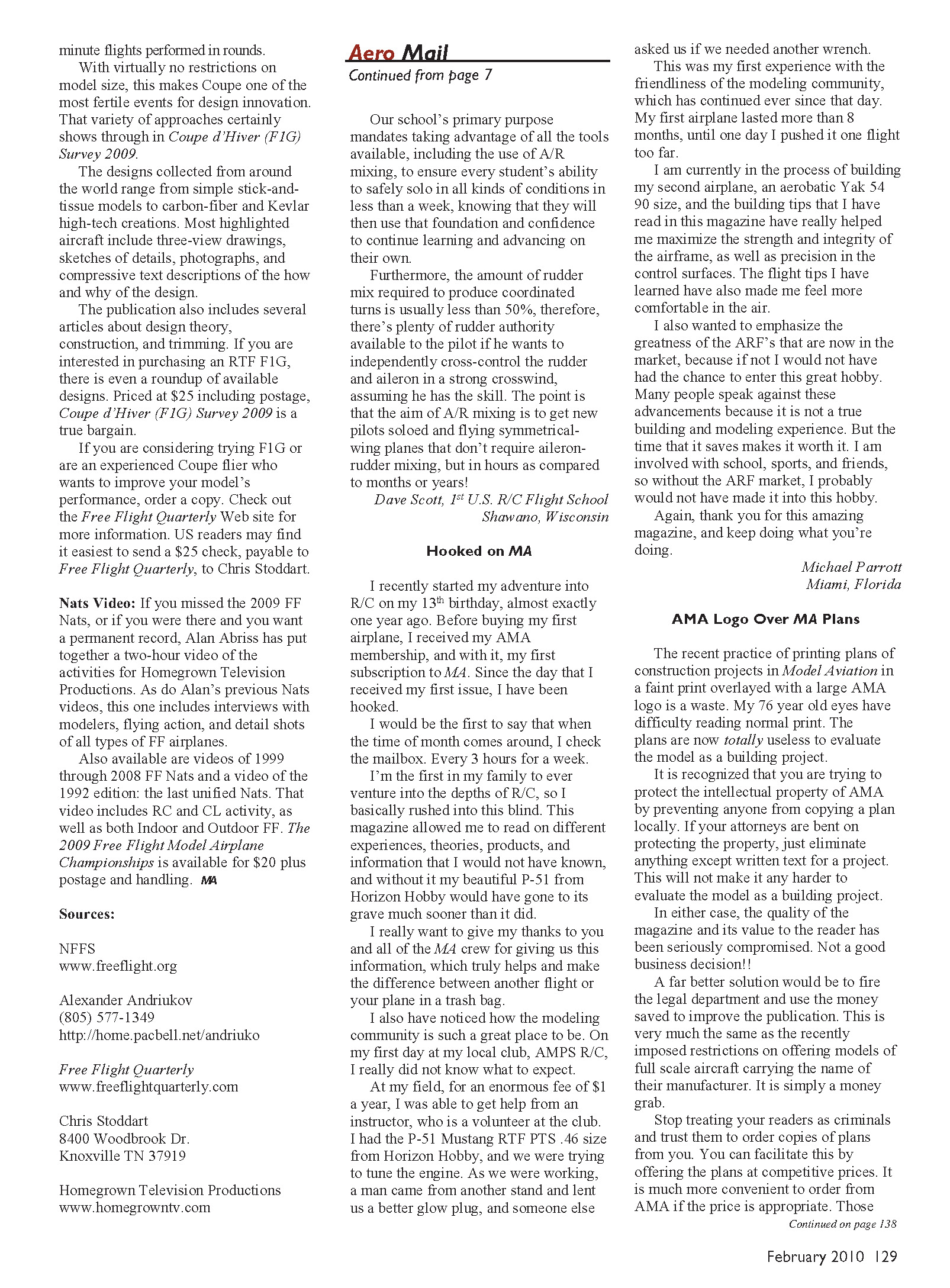
- Attach the paper outline to a piece of 1/4-inch plywood. Cut and sand to exact shape. Use this pattern to cut a fixture base from 3/4-inch birch plywood. Use the same pattern to cut blade blanks from 1/2-inch balsa.
- (Tip) The most accurate way to make duplicate parts from thick wood is to rough-cut the piece and then use a router mounted in a router table fitted with a flush-trim bit. This bit has a ball bearing that rides against the pattern while the router cuts the part to the exact size and shape of the pattern.
- Drill holes for blade fittings or add a hardwood root reinforcement while the blanks are still oversized.
- Measure the exact chord width of the pattern at each of the radius stations. If the blade has a nonsymmetrical area distribution, measure the semichord from LE to centerline and from TE to centerline.
- Also measure the exact thickness of the balsa blade blanks (close to 1/2 inch) and the exact thickness of the 3/4-inch plywood base (this will usually be slightly less than 3/4 inch). Use a dial caliper for maximum accuracy.
- Figure out how much to rotate the blade so it will fit within the 1/2-inch balsa plank. Rotating the blade so that the blade angle at maximum blade width goes to zero will typically allow the blade to fit. Then reduce the blade angle at all of the other stations. If the blade angle is 30° at the station with maximum width, you would deduct 30° from all other blade angles. The rotated blade angles from that point out to the tip will be negative numbers.
- Use the chord measurements and rotated blade angles to calculate the exact location of the LE and TE relative to the zero-rotated-angle station. For a blade with symmetrical area distribution, divide the chord by 2 and multiply by the tangent of the rotated blade angle at that station. For a nonsymmetrical area distribution, use the semichord measurement.
- Check to make sure that the total LE and TE offset at each station is at least 3/32 inch less than the 1/2-inch balsa-blank thickness. If this is not the case, select another station, rotate the blade angle to zero there, and try again.
- Add each measurement from the previous step to half the balsa-blank thickness plus the exact thickness of the 3/4-inch plywood base. Organize these numbers in tabular form for clarity.
- To make the sides for the fixture, cut a piece of 1/32-inch plywood to approximately 4 inches wide, its length slightly longer than that of the 1/4-inch plywood pattern. Carefully curve the 1/32-inch plywood around the pattern and mark the location of each station. Extend the station lines across the 1/32-inch plywood sheet, perpendicular to the long edge. Mark one long edge as LE and the other as TE. Carefully transfer the final measurements to the 1/32-inch plywood (offset plus half balsa-blank thickness plus 3/4-inch plywood thickness). Connect these points to create a curved line for the LE and another for the TE.
- The LE line should curve down from the root toward the tip; the TE line should curve up from the root to the tip. The height of both LE and TE curves should be the same at the station where the rotated blade angle is zero.
- Cut along the curved lines to make each fixture side. Glue the 1/32-inch plywood fixture sides to the 3/4-inch plywood block, flush with the bottom.
- After the glue dries, fit a balsa blade blank into the fixture. Cut some strips of 1/32-inch basswood to approximately 1/8 inch wide and slightly longer than the blade blank. Position a basswood strip against the balsa blank and tight against the LE 1/32-inch plywood fixture side. Carefully glue the basswood to the blade blank using thin CA. Repeat for the TE.
- Remove the blade blank from the fixture. Use a modeling knife to carve away the back face of the balsa, using the 1/32-inch basswood edge strips as guides. Sand in undercamber, checking frequently with templates. (I use laser-cut steel templates from Alexander Andriukov.) Turn the blade over to carve and sand the front face.
- Finish the blades as desired, then mount on the hub so each blade is at the correct pitch. You put back in the degrees of blade angle you took out when you rotated the blade to fit it into the 1/2-inch balsa blank.
For more about blade-carving methods, see “Propeller Construction” in the 1988 NFFS Symposium. For tips about molded blades, see “Composite Construction of Propeller Blades for F1B” in the 1997 Symposium.
Coupe Survey
Sergio Montes and the staff at Free Flight Quarterly have released an updated Coupe d’Hiver (F1G) Survey 2009. The new version is a two-volume set that totals more than 110 pages and includes two full-size Coupe plans.
Maurice Bayet, a French modeler and magazine editor, originated the Coupe d’Hiver event in 1939 as an F1G competition to be held in the winter. (Coupe d’Hiver means “winter cup”.)
In the last few years, it has become one of the most popular FAI F1G test events. The “mini” events typically use smaller models and are flown to two-minute maxes instead of the three-minute maxes used for the “big” FAI events. Rules for F1G are simple: they allow 10 grams of rubber, an 80-gram minimum all-up weight, and five two-minute maxes (plus 15-second up and down). The Coupe Survey is an excellent resource, with articles on design, construction, and setup, and numerous photos and plans. The set is available from Free Flight Quarterly; contact info is in the survey.
Nats Video Available
A DVD of the 2009 Nats Free Flight Championships is now available. The video includes coverage of the major events, interviews with winners, and highlights from the week. Contact the NFFS website for ordering details.
If you missed the 2009 FF Nats, or if you were there and want a permanent record, Alan Abriss has put together a two-hour video of the activities for Homegrown Television Productions. As with Alan’s previous Nats videos, this one includes interviews with modelers, flying action, and detail shots of all types of free-flight airplanes.
Also available are videos of the 1999 through 2008 FF Nats and a video of the 1992 edition—the last unified Nats. That video includes RC and CL activity, as well as both indoor and outdoor free flight. The 2009 Free Flight Model Airplane Championships DVD is available for $20 plus postage and handling.
Sources
- NFFS — www.freeflight.org
- Alexander Andriukov — (805) 577-1349 — http://home.pacbell.net/andriuko
- Free Flight Quarterly — www.freeflightquarterly.com
- Chris Stoddart — 8400 Woodbrook Dr., Knoxville TN 37919
- Homegrown Television Productions — www.homegrowntv.com
Transcribed from original scans by AI. Minor OCR errors may remain.

