
Free Flight Duration
Louis Joyner [[email protected]]
As seen at the AMA Nats
One of the most enjoyable, and purposeful, reasons for going to a contest is meeting other aeromodelers and seeing what new ideas they have. Following are some innovative tips seen at the 2010 Nats.
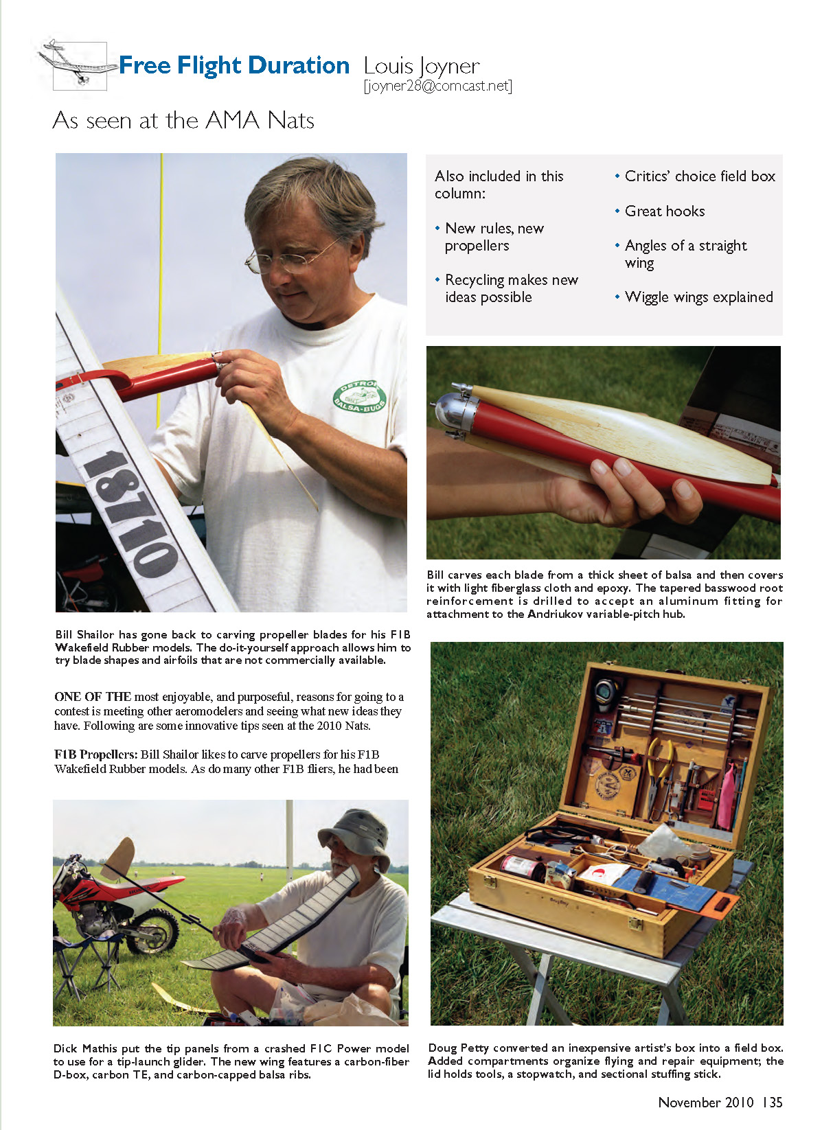
F1B Propellers
Bill Shailor likes to carve propellers for his F1B Wakefield rubber models. As do many other F1B fliers, he had been using the excellent carved-balsa Andriukov blades. But last year he switched to fashion his own.
“The Andriukov blades were designed for 40-gram motors,” said Bill. Rules changes have reduced the allowable motor weight to 30 grams, or approximately an ounce.
“My new blades are narrower and thinner, at least a third thinner, maybe more,” he said. Bill has also reduced blade undercamber and slimmed the blade near the root. In addition, he has increased tip washout and increased pitch. “I’m up to 26 to 27 inches at rest,” he said.
As do most F1B fliers, Bill uses a torque-actuated, variable-pitch hub that decreases pitch during the flight to roughly match the decreasing torque of the rubber motor. “At rest” refers to the lower pitch setting.
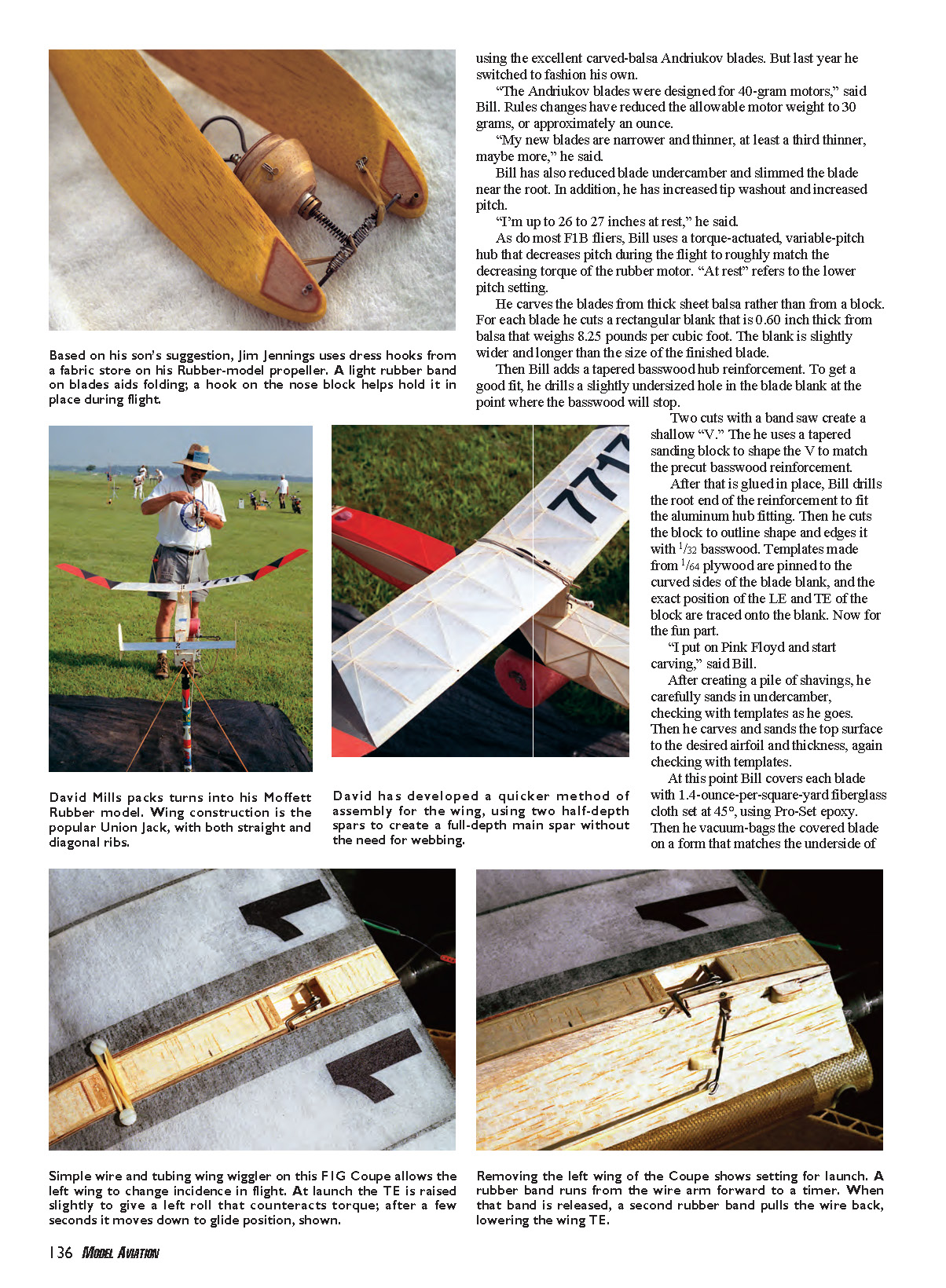
He carves the blades from thick sheet balsa rather than from a block. For each blade he cuts a rectangular blank that is 0.60 inch thick from balsa that weighs 8.25 pounds per cubic foot. The blank is slightly wider and longer than the size of the finished blade.
Then Bill adds a tapered basswood hub reinforcement. To get a good fit, he drills a slightly undersized hole in the blade blank at the point where the basswood will stop. Two cuts with a band saw create a shallow “V.” He uses a tapered sanding block to shape the V to match the precut basswood reinforcement. After that is glued in place, Bill drills the root end of the reinforcement to fit the aluminum hub fitting. Then he cuts the block to outline shape and edges it with 1/32 basswood. Templates made from 1/64 plywood are pinned to the curved sides of the blade blank, and the exact position of the LE and TE of the block are traced onto the blank.
“I put on Pink Floyd and start carving,” said Bill. After creating a pile of shavings, he carefully sands in undercamber, checking with templates as he goes. Then he carves and sands the top surface to the desired airfoil and thickness, again checking with templates.
At this point Bill covers each blade with 1.4-ounce-per-square-yard fiberglass cloth set at 45°, using Pro-Set epoxy. Then he vacuum-bags the covered blade on a form that matches the underside of the blade. Teflon-coated bleeder felt is used to absorb excess epoxy resin.
Bill sands the blade with progressively finer sandpaper, ending with 2,000 grit. A final polishing completes the process.
In the last year or so, Bill has made 13 pairs of blades. See the February 2010 Duration column for more about carving blades.
Recycling
A half-century ago it was common practice for an aeromodeler to raid his or her supply of leftover components to make a “new” airplane. My older brother fitted a Fubar wing and stabilizer to a simple stick fuselage to make a quick rubber model. I even flew a Wakefield with a T-Bird wing at the 1960 Nats.
But this early form of recycling seems to have fallen out of favor. Gas models, the source of those wings and stabilizers from the past, now last much longer. In the days before epoxy and better fuel-proofing, high-nitro fuels took their toll on gas-model fuselages, leaving orphaned wings and stabilizers.
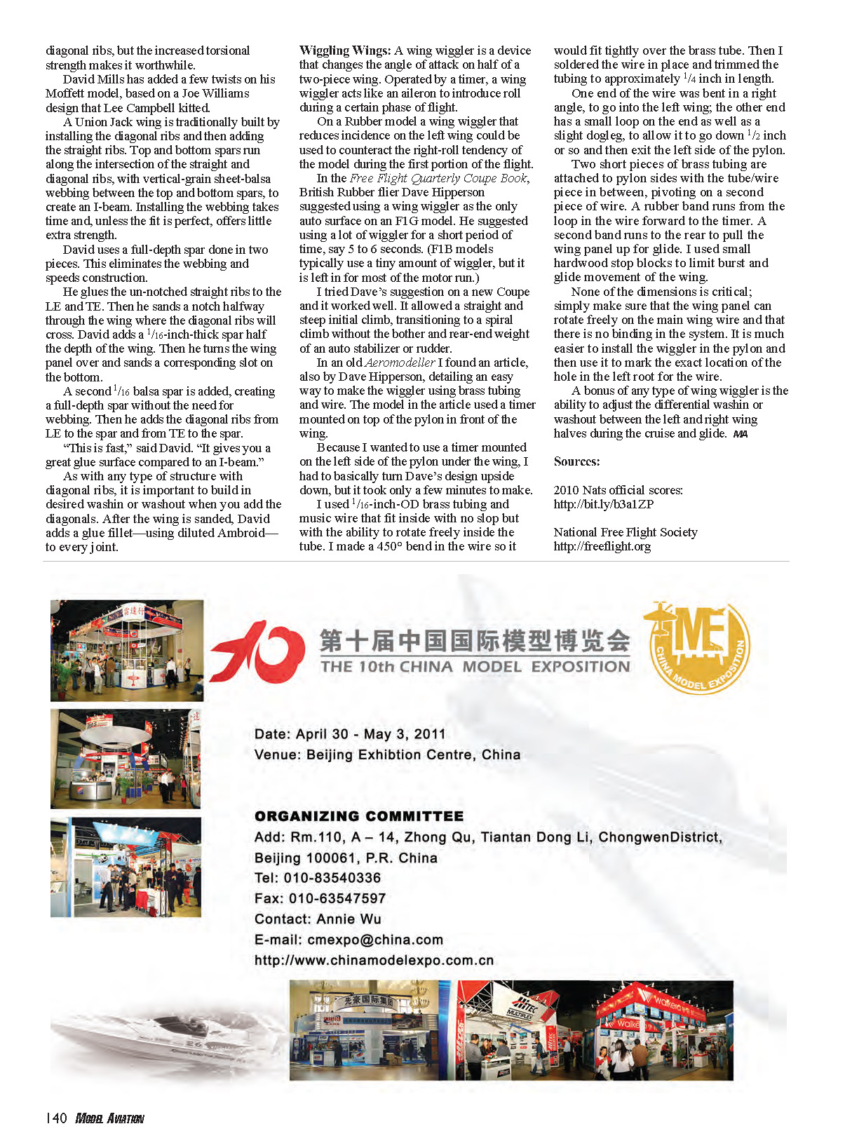
However, Dick Mathis has revived the practice. His tip-launch glider uses the tips from an F1C power model. A crash, rather than fuel-soaked old age, made the carbon D-box tips from a six-panel wing available.
“It’s called repurposing,” he said.
Unlike most sheet-balsa catapult-glider wings, the wing is undercambered, not flat-bottomed.
“It’s way undercambered,” said Dick. “It gets higher than my conventional ones; it’s faster.”
The wing is attached to the fuselage with screws, allowing removal for transportation. A carbon peg running through the left tip provides finger grips for tip launch.
As do more and more free-flight models, the glider uses RDT (remote DT) to allow flight termination at will. This makes test-flying more convenient by allowing the flier to terminate the flight if an adjustment is needed and, more important, permits test-flying on a small field with minimum risk of going off-field or into a tree.
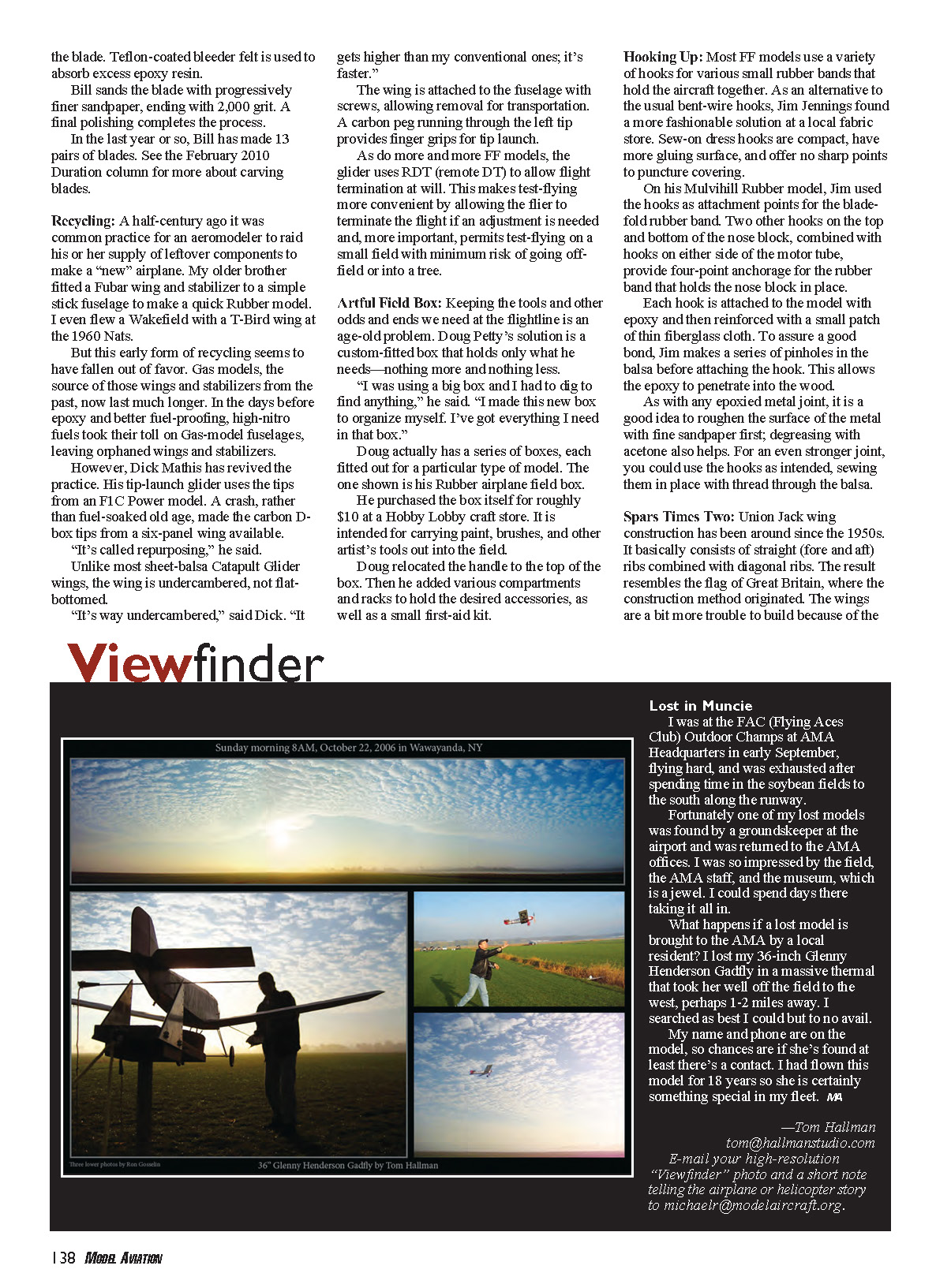
Artful Field Box
Keeping the tools and other odds and ends we need at the flightline is an age-old problem. Doug Petty’s solution is a custom-fitted box that holds only what he needs—nothing more and nothing less.
“I was using a big box and I had to dig to find anything,” he said. “I made this new box to organize myself. I’ve got everything I need in that box.”
Doug actually has a series of boxes, each fitted out for a particular type of model. The one shown is his rubber-airplane field box.
He purchased the box itself for roughly $10 at a Hobby Lobby craft store. It is intended for carrying paint, brushes, and other artist’s tools out into the field.
Doug relocated the handle to the top of the box. Then he added various compartments and racks to hold the desired accessories, as well as a small first-aid kit.
Hooking Up
Most free-flight models use a variety of hooks for various small rubber bands that hold the aircraft together. As an alternative to the usual bent-wire hooks, Jim Jennings found a more fashionable solution at a local fabric store. Sew-on dress hooks are compact, have more gluing surface, and offer no sharp points to puncture covering.
On his Mulvihill rubber model, Jim used the hooks as attachment points for the blade-fold rubber band. Two other hooks on the top and bottom of the nose block, combined with hooks on either side of the motor tube, provide four-point anchorage for the rubber band that holds the nose block in place.
Each hook is attached to the model with epoxy and then reinforced with a small patch of thin fiberglass cloth. To assure a good bond, Jim makes a series of pinholes in the balsa before attaching the hook. This allows the epoxy to penetrate into the wood.
As with any epoxied metal joint, it is a good idea to roughen the surface of the metal with fine sandpaper first; degreasing with acetone also helps. For an even stronger joint, you could use the hooks as intended, sewing them in place with thread through the balsa.
Spars Times Two
Union Jack wing construction has been around since the 1950s. It basically consists of straight (fore and aft) ribs combined with diagonal ribs. The result resembles the flag of Great Britain, where the construction method originated. The wings are a bit more trouble to build because of the diagonal ribs and additional joints, but they can provide good rigidity and neat load distribution when done carefully.
Wiggling Wings
A wing wiggler is a device that changes the angle of attack on half of a two-piece wing. Operated by a timer, a wing wiggler acts like an aileron to introduce roll during a certain phase of flight.
On a rubber model, a wing wiggler that reduces incidence on the left wing could be used to counteract the right-roll tendency of the model during the first portion of the flight.
In the Free Flight Quarterly Coupe Book, British rubber flier Dave Hipperson suggested using a wing wiggler as the only auto surface on an F1G model. He suggested using a lot of wiggler for a short period of time, say 5 to 6 seconds. (F1B models typically use a tiny amount of wiggler, but it is left in for most of the motor run.)
I tried Dave's suggestion on a new coupe and it worked well. It allowed a straight and steep initial climb, transitioning to a spiral climb without the bother and rear-end weight of an auto stabilizer or rudder.
In an old Aeromodeller I found an article, also by Dave Hipperson, detailing an easy way to make the wiggler using brass tubing and wire. The model in the article used a timer mounted on top of the pylon in front of the wing.
Because I wanted to use a timer mounted on the left side of the pylon under the wing, I had to basically turn Dave's design upside down, but it took only a few minutes to make.
I used 1/16-inch-OD brass tubing and music wire that fit inside with no slop but with the ability to rotate freely inside the tube. I made a 45° bend in the wire so it would fit tightly over the brass tube. Then I soldered the wire in place and trimmed the tubing to approximately 1/4 inch in length.
One end of the wire was bent in a right angle, to go into the left wing; the other end has a small loop on the end as well as a slight dogleg, to allow it to go down 1/2 inch or so and then exit the left side of the pylon.
Two short pieces of brass tubing are attached to the pylon sides with the tube/wire piece in between, pivoting on a second piece of wire. A rubber band runs from the loop in the wire forward to the timer. A second band runs to the rear to pull the wing panel up for glide. I used small hardwood stop blocks to limit burst and glide movement of the wing.
None of the dimensions is critical; simply make sure that the wing panel can rotate freely on the main wing wire and that there is no binding in the system. It is much easier to install the wiggler in the pylon and then use it to mark the exact location of the hole in the left root for the wire.
A bonus of any type of wing wiggler is the ability to adjust the differential washin or washout between the left and right wing halves during the cruise and glide.
Sources
- 2010 Nats official scores: http://bit.ly/b3a1ZP
- National Free Flight Society: http://freeflight.org
Transcribed from original scans by AI. Minor OCR errors may remain.

