
Free Flight Duration
Louis Joyner [[email protected]]
FF World Champs team selected for 2011
THIS PAST FALL a nine-man team was selected to represent the US at the Free Flight World Championships, to be held this May in Embalse, Argentina. The members are:
- F1A Towline Glider: Brian Van Nest, Robert Sifleet, Jim Parker
- F1B Wakefield Rubber: Alex Andriukov, Robert Tymchek, Dave Saks
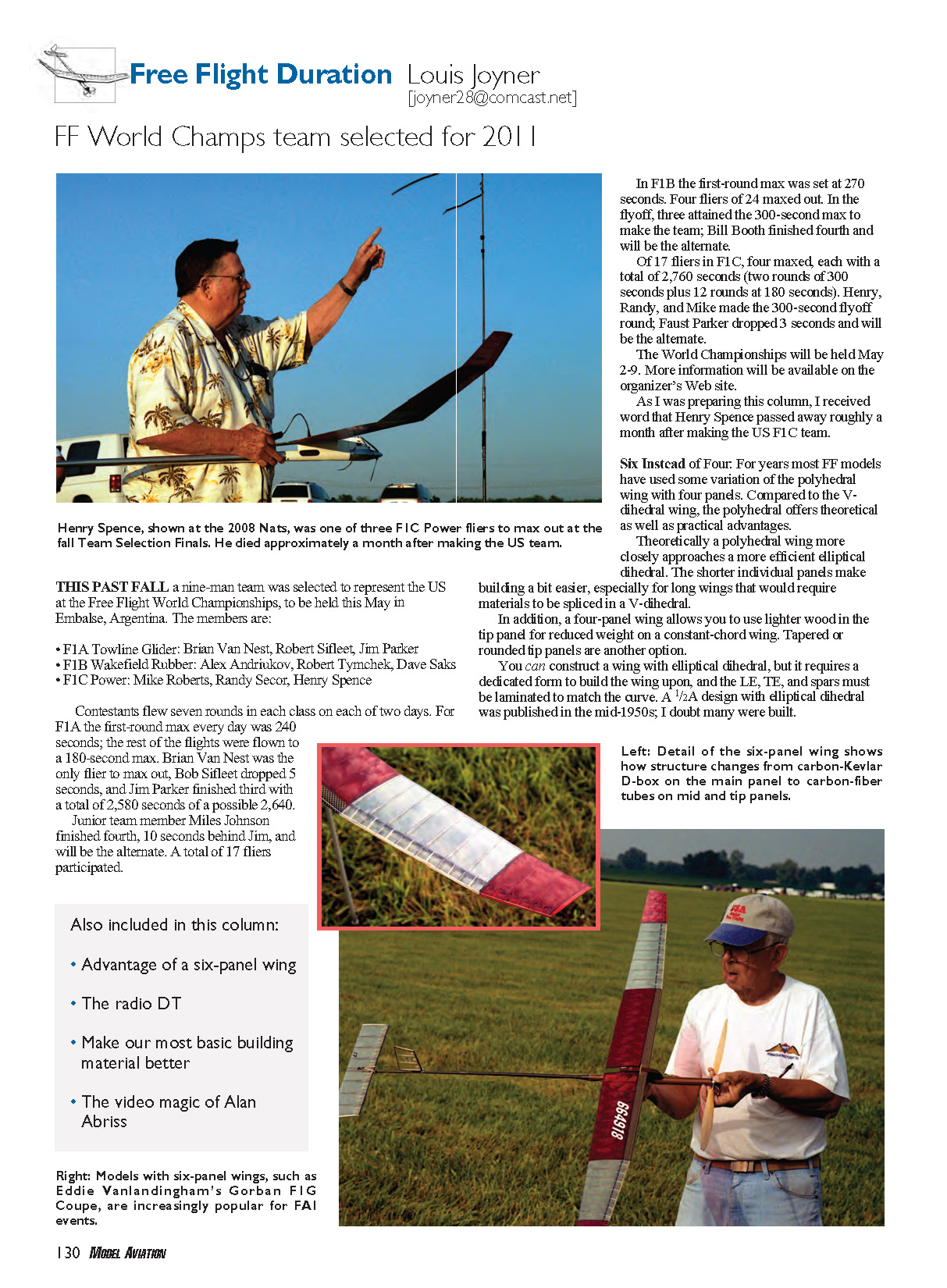
- F1C Power: Mike Roberts, Randy Secor, Henry Spence
Contestants flew seven rounds in each class on each of two days. For F1A the first-round max every day was 240 seconds; the rest of the flights were flown to a 180-second max. Brian Van Nest was the only flier to max out, Bob Sifleet dropped 5 seconds, and Jim Parker finished third with a total of 2,580 seconds of a possible 2,640.
Junior team member Miles Johnson finished fourth, 10 seconds behind Jim, and will be the alternate. A total of 17 fliers participated.
In F1B the first-round max was set at 270 seconds. Four fliers of 24 maxed out. In the flyoff, three attained the 300-second max to make the team; Bill Booth finished fourth and will be the alternate.
Of 17 fliers in F1C, four maxed, each with a total of 2,760 seconds (two rounds of 300 seconds plus 12 rounds at 180 seconds). Henry, Randy, and Mike made the 300-second flyoff round; Faust Parker dropped 3 seconds and will be the alternate.
The World Championships will be held May 2–9. More information will be available on the organizer's web site.
As I was preparing this column, I received word that Henry Spence passed away roughly a month after making the US F1C team.
Six Instead of Four
For years most FF models have used some variation of the polyhedral wing with four panels. Compared to the V-dihedral wing, the polyhedral offers theoretical as well as practical advantages.
Theoretically a polyhedral wing more closely approaches a more efficient elliptical dihedral. The shorter individual panels make building a bit easier, especially for long wings that would require materials to be spliced in a V-dihedral.
In addition, a four-panel wing allows you to use lighter wood in the tip panel for reduced weight on a constant-chord wing. Tapered or rounded tip panels are another option.
You can construct a wing with elliptical dihedral, but it requires a dedicated form to build the wing upon, and the LE (leading edge), TE (trailing edge), and spars must be laminated to match the curve. A 1/2A design with elliptical dihedral was published in the mid-1950s; I doubt many were built.
With materials in hand, I looked at six-panel wings in earnest. The first panel is normally nearly 46–48% of the wing semispan, the middle panel is approximately 35–37%, and the tip panel is 17–18%.
Wing chords on Eugene Verbitsky’s #72 F1C Power model went from 100% at the root to 87.5% at the first break, to 62.5% at the second break, and down to 37.5% at the tip. A root chord of 160 mm (close to 6.4 inches) gives a tip chord of 60 mm (2.4 inches). For my F1G I intended to use a root chord of 120 mm (approximately 4.72 inches); using Eugene’s 37.5% for the tip chord would yield a tip chord of 45 mm, less than 2 inches. That might work fine for a fast-gliding F1C model, but I was afraid that the Reynolds number at the tip on a slow Coupe would be lower than I felt comfortable with. So I fudged the tip chord up to 70 mm (roughly 2.75 inches).
For more modern wings with carbon-fiber D-boxes, a curved mold is needed for each wing half in addition to the curved building board.
Although six-panel wings with two dihedral breaks on each side have been around for a number of years, their popularity has been increasing—especially in FAI events. One advantage of using six panels is that it allows the dihedral to more closely approach elliptical dihedral. By using two dihedral breaks on each wing half, the angle between two adjacent panels can be kept lower, reducing interference drag at the break.
Interference drag is caused by air flowing over the upper surface of adjacent panels having to crowd into less space spanwise as it flows back toward the wing high point. Henry Cole and Lee Hines have suggested that keeping the dihedral angle between adjacent panels below 15° helps reduce interference drag. With a six-panel wing you can use two shallow dihedral angles to get the necessary rise at the tip.
Six panels also allow a triple-tapered planform that more closely matches an elliptical planform while using straight components. Now FF models typically use something that resembles a half ellipse, with a straight TE, rather than the traditional full ellipse of a Spitfire wing. One advantage of an elliptical wing or a six-panel wing is that the tip chord can be quite small, to reduce drag.
Perhaps the biggest practical advantage of a six-panel wing is that you can build a longer wing using available components such as D-box skins and spars. And you can do it on an existing building board or undercambered wing fixture.
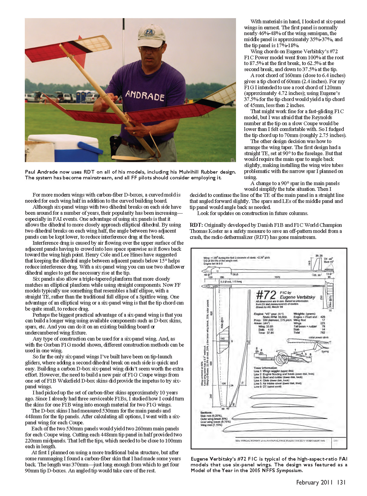
Any type of construction can be used for a six-panel wing. And, as with the Gorban F1G model shown, different construction methods can be used in one wing.
So far the only six-panel wings I’ve built have been on tip-launch gliders, where adding a second dihedral break on each side is quick and easy. Building a carbon D-box six-panel wing didn’t seem worth the extra effort. However, the need to build a new pair of F1G Coupe wings from one set of F1B Wakefield D-box skins did provide the impetus to try six-panel wings.
I had picked up the set of carbon-fiber skins approximately 10 years ago. Since I already had three serviceable F1Bs, I studied how I could turn the skins for one F1B wing into enough material for two F1G wings.
The D-box skins I had measured 530 mm for the main panels and 448 mm for the tip panels. After calculating all options, I went with a six-panel wing for each Coupe.
- Each of the two 530 mm panels would yield two 260 mm main panels for each Coupe wing.
- Cutting each 448 mm tip panel in half provided two 220 mm mid panels.
- That left the tips, which needed to be close to 100 mm each in length.
At first I planned on using a more traditional balsa structure, but after some rummaging I found a carbon-fiber skin that I had made some years back. The length was 370 mm—just long enough from which to get four 90 mm tip D-boxes. An angled tip would take care of the rest.
The other design decision was how to arrange the wing taper. The first design had a straight TE, set at 90° to the fuselage. But that would require the main spar to angle back slightly, making installing the wing wire tubes problematic with the narrow spar I planned on using.
A change to a 90° spar in the main panels would simplify the tube situation. Then I decided to continue the line of the TE of the main panel in a straight line that angled forward slightly. The spars and LEs of the middle panel and tip panel would angle back as needed.
Look for updates on construction in future columns.
RDT
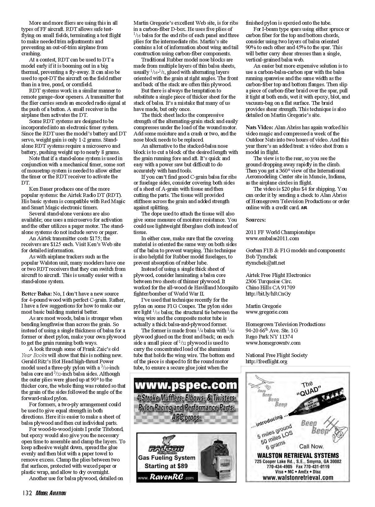
Originally developed by Danish F1B and F1C World Champion Thomas Koster as a safety measure to save an off-pattern model from a crash, the radio dethermalizer (RDT) has gone mainstream. More and more fliers are using this in all types of FF aircraft. RDT allows safe test-flying on small fields, terminating a test flight to make needed trim adjustments and preventing an out-of-trim airplane from crashing.
At a contest, RDT can be used to DT a model early if it is booming out in a big thermal, preventing a fly-away. It can also be used to spot-DT the aircraft on the field rather than in a tree, pond, or cornfield.
RDT systems work in a similar manner to remote garage-door openers. A transmitter that the flier carries sends an encoded radio signal at the push of a button. A small receiver in the airplane then activates the DT.
Some RDT systems are designed to be incorporated into an electronic timer system. Since the RDT uses the model's battery and DT servo, weight gain is only 1–2 grams. Stand-alone RDT systems require a microservo and battery, pushing weight up to nearly 8 grams.
Note that if a stand-alone system is used in conjunction with a mechanical timer, some sort of mousetrap system is needed to allow either the timer or the RDT receiver to activate the DT.
Ken Bauer produces one of the more popular systems: the Airtek Radio DT (RDT). His basic system is compatible with Red Magic and Smart Magic electronic timers.
Several stand-alone versions are also available; one uses a microservo for activation and the other utilizes a pager motor. The stand-alone systems do not include servo or pager.
An Airtek transmitter costs $175; the receivers are $125 each. Visit Ken's web site for detailed information.
As with airplane trackers such as the popular Walston unit, many modelers have one or two RDT receivers that they can switch from aircraft to aircraft. This is usually easier with a stand-alone system.
Better Balsa
No, I don't have a new source for 4-pound wood with perfect C-grain. Rather, I have a few suggestions for how to make our most basic building material better.
As are most woods, balsa is stronger when bending lengthwise than across the grain. So instead of using a single thickness of balsa for a former or sheet pylon, make your own plywood to get the grain running both ways.
A look through some of Frank Zaic's old Year Books will show that this is nothing new. Gerald Ritz's Hot Head high-thrust Power model used a three-ply pylon with a 1/16-inch balsa core and 1/32-inch balsa sides. Although the outer plies were glued up at 90° to the thicker core, the whole thing was rotated so that the grain of the sides followed the angle of the forward-raked pylon.
For formers, a two-ply arrangement could be used to give equal strength in both directions. Here it is easier to make a sheet of balsa plywood and then cut individual parts.
For wood-to-wood joints I prefer Titebond, but epoxy would also give you the necessary open time to assemble and clamp the layers. To keep adhesive weight down, spread the glue evenly and then blot with a paper towel to remove excess. Clamp the plies between two flat surfaces, protected with waxed paper or plastic wrap, and allow to dry overnight.
Another use for balsa plywood, detailed on Martin Gregorie's excellent web site, is for ribs in a carbon-fiber D-box. He uses five plies of 1/16 balsa for the end ribs of each panel and three plies for the intermediate ribs. Martin's site contains a lot of information about wing and tail construction using carbon-fiber components.
Traditional Rubber model nose blocks are made from multiple layers of thin balsa sheets, usually 1/16–1/8, glued with alternating layers oriented with the grain at right angles. The front and back of the stack are often thin plywood.
But there is always the temptation to substitute a single piece of thicker sheet for the stack of balsa. It's a mistake that many of us have made, but only once. The thick sheet lacks the compressive strength of the alternating-grain stack and easily compresses under the load of the wound motor. Add some moisture and a crash or two, and the nose block needs to be replaced.
An alternative to the stacked-balsa nose block is to cut a block of the desired length with the grain running fore and aft. It's quick and easy with a power saw but difficult to do accurately with hand tools.
If you can't find good C-grain balsa for ribs or fuselage sides, consider covering both sides of a sheet of A-grain with tissue and then cutting the parts. The tissue will provide stiffness across the grain and added strength against splitting. The dope used to attach the tissue will also give some measure of moisture resistance. You could use lightweight fiberglass cloth instead of tissue.
In either case, make sure that the covering material is oriented the same way on both sides of the balsa to prevent warping. This technique is also helpful for Rubber model fuselages, to prevent absorption of rubber lube.
Instead of using a single thick sheet of plywood, consider laminating a balsa core between two sheets of thinner plywood. It worked for the all-wood de Havilland Mosquito fighter/bomber of World War II.
I've used that technique recently for the pylon on some F1G Coupes. The pylon sides are light 1/16 balsa; the structural tie between the wing wire and the composite motor tube is actually a thick balsa-and-plywood former.
The former is made from 1/4 balsa with 1/64 plywood glued on the front and back; on each side a small piece of 1/32 plywood is used to carry the concentrated load of the aluminum tube that holds the wing wire. The bottom end of the piece is shaped to fit the round motor tube, to ensure a secure glue joint when the finished pylon is epoxied onto the tube.
For I-beam type spars using either spruce or carbon fiber for the top and bottom chords, consider using two layers of balsa oriented 90° to each other and 45° to the spar. This will better carry shear stresses than a single, vertical-grained balsa web.
An easier but more expensive solution is to use a carbon-balsa-carbon spar with the balsa running spanwise and the same width as the carbon-fiber top and bottom flanges. Then slip a piece of carbon-fiber braid over the spar, pull it tight at both ends, wet it with epoxy, blot, and vacuum-bag on a flat surface. The braid provides shear strength. This technique is also detailed on Martin Gregorie's site.
Nats Video
Alan Abriss has again worked his video magic and compressed a week of the Outdoor Nats into two hours of video. And this year there's an added treat: a video shot from a model in flight.
The view is to the rear, so you see the ground dropping away rapidly in the climb. Then you get a 360° view of the International Aeromodeling Center site in Muncie, Indiana, as the airplane circles in flight.
The video is $20 plus $4 for shipping. You can order it by sending a check to Alan Abriss of Homegrown Television Productions or order online with a credit card. MA
Sources
- 2011 FF World Championships: www.embalse2011.com
- Gorban F1B & F1G models and components: Bob Tymchek, [email protected]
- Airtek Free Flight Electronics: 2306 Turquoise Cir., Chino Hills CA 91709 — http://bit.ly/hRrCngy
- Martin Gregorie: www.gregorie.com
- Homegrown Television Productions: 94-20 66th Ave. Ste. 1G, Rego Park NY 11374 — www.homegrowntv.com
- National Free Flight Society: http://freeflight.org
Transcribed from original scans by AI. Minor OCR errors may remain.

