
FREE FLIGHT INDOOR
Bud Tenny, Box 830545, Richardson TX 75083
IN A PREVIOUS column I wrote that access to the Santa Ana, California, hangars had collapsed from lack of maintenance. Actually, an earlier report stated that disagreements between the Marines and the city of Santa Ana had resulted in loss of access.
Big Model
Several years ago at one of the hangars on the Santa Ana Marine Corps Air Field, Hermann Andresen flew a large model, trying for a 60-minute flight. When I asked him for details on the aircraft, he gave the following report.
“I had a 60-inch-span, 600-square-inch [EZ60] that was flown in Santa Ana several times. It was a prototype to check the viability of turning tight with a large model.
“Erv Rodemsky and Bud Romak had made similar size models which showed the potential, but these models demonstrated a major drawback in this approach. The models had such wide turns it was hard to keep them in the building. Computer studies published in an NFFS (National Free Flight Society) Symposium report verified that this was the easiest route to high performance.
“My prototype used differential wing chord (steadily increasing wing chord, increasing linearly to the left tip) and rudder offset to obtain more efficient turns. It could be flown easily in a single basketball court gym, using about half the court width.
“The last time I took it to the hangar, I opened the box to find a rat had used the materials to build a nest. End of experiment. Then after timing Steve Brown’s 63:54 flight, I realized it had become obsolete anyway.
“Some of my studies showed interesting results: a 30-square-inch model would have to be kept to 0.001 ounce weight to be capable of 60-minute flights. A 600-square-inch airplane could have over seven times that wing loading for similar performance.”
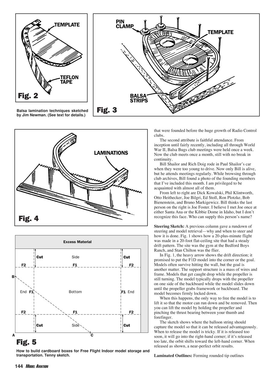
Detroit Balsa Bugs
The Balsa Bugs club has at least two interesting attributes. One is that it was founded before World War II. It isn't the oldest US club, but it is well ahead of most that were founded before the huge growth of Radio Control clubs. The second attribute is faithful attendance. From inception until fairly recently, including all through World War II, Balsa Bugs club meetings were held once a week. Now the club meets once a month, still with no break in continuity.
Bill Shailor and Rich Doig rode in Paul Shailor’s car when they were too young to drive. Now only Bill is alive, but he attends meetings regularly. While browsing through club archives, Bill found a photo of the founding members that I’ve included this month. I am privileged to be acquainted with almost all of them.
From left to right are Dick Kowalski, Phil Klintworth, Otto Heithecker, Joe Bilgri, Ed Stoll, Ron Plotzke, Bob Bienenstein, and Bruno Markigewicz. Bill thinks the last person on the right is Joe Foster. I believe I met Joe once at either Santa Ana or the Kibbie Dome in Idaho, but I don’t recognize this face. Who can supply this person’s name?
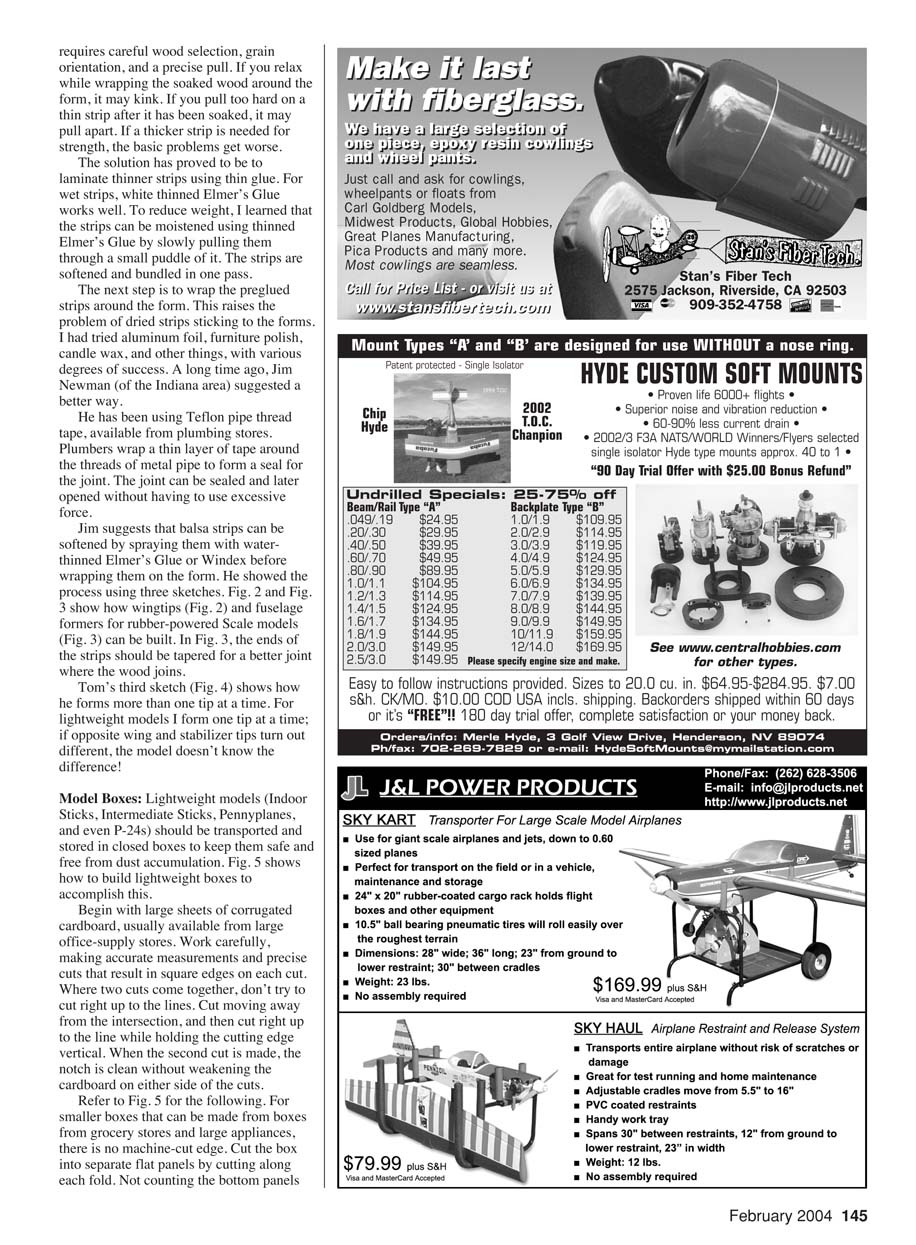
Steering Sketch
A previous column gave a rundown of steering and model retrieval—why and when to steer and how it is done. Fig. 1 shows how a 20-plus-minute flight was made in a 20-foot flat-ceiling site that had a steady drift pattern. The site was the gym at the Bedford Boys Ranch, and Stan Chilton was the flier.
In Fig. 1, the heavy arrow shows the drift direction; it promised to put the F1D model into the corner or the goal. Models often survive hitting the wall, but the goal is another matter. The support structure is a mass of wires and frame. Models that get caught drop while the propeller is still turning. The model typically drops with the propeller on one side of the backboard while the model slides down until the propeller grabs framework or backboard. The model becomes firmly locked down.
When this happens, the only way to free the model is to lift it so that the motor can run down and be removed. Then you can lift the model by holding the propeller and pinching the thrust bearing between your thumb and forefinger.
The sketch shows where the balloon string should capture the model so that it can be released advantageously. When to release the model is tricky. If it is released too soon, it will go into the right-hand corner; if it's released too late, the orbit shifts toward the left-hand corner. When released as shown, a near-perfect orbit results.
Laminated Outlines: Forming rounded tip outlines
Three commonly used approaches to forming laminated outlines are shown in Figs. 2, 3, and 4.
- Fig. 2: A template is used and successive thin laminations are glued to the template and held with Teflon tape until dry.
- Fig. 3: A pin-clamp method where the template is pinned to a building board and the laminations are glued in place and held with balsa strips. For heavier laminations it is often easier to build up narrow sections and splice them together.
- Fig. 4: Laminations built on a notched form that helps hold the laminations while the glue dries.
After the laminations have set, fair the outline with a sanding block. This requires careful wood selection, grain orientation, and a precise pull. If you relax while wrapping the soaked wood around the form, it may kink. If you pull too hard on a thin strip after it has been soaked, it may pull apart. If a thicker strip is needed for strength, then the basic problems get worse.
The solution has proved to be to laminate thinner strips using thin glue. For wet strips, white thinned Elmer's Glue works well. To reduce weight, I learned that the strips can be moistened using thinned Elmer's Glue by slowly pulling them through a small puddle of it. The strips are softened and bundled in one pass.
The next step is to wrap the preglued strips around the form. This raises the problem of dried strips sticking to the forms. I had tried aluminum foil, furniture polish, candle wax, and other things, with various degrees of success. A long time ago, Jim Newman (of the Indiana area) suggested a better way.
He has been using Teflon pipe thread tape, available from plumbing stores. Plumbers wrap a thin layer of tape around the threads of metal pipe to form a seal for the joint. The joint can be sealed and later opened without having to use excessive force.
Jim suggests that balsa strips can be softened by spraying them with water-thinned Elmer's Glue or Windex before wrapping them on the form. He showed the process using three sketches. Fig. 2 and Fig. 3 show how wingtips (Fig. 2) and fuselage formers for rubber-powered Scale models (Fig. 3) can be built. In Fig. 3, the ends of the strips should be tapered for a better joint where the wood joins.
His third sketch (Fig. 4) shows how he forms more than one tip at a time. For lightweight models I form one tip at a time; if opposite wing and stabilizer tips turn out different, the model doesn't know the difference!
Model Boxes
Lightweight models (Indoor Sticks, Intermediate Sticks, Pennyplanes, and even P-24s) should be transported and stored in closed boxes to keep them safe and free from dust accumulation. Fig. 5 shows how to build lightweight boxes to accomplish this.
Begin with large sheets of corrugated cardboard, usually available from large office-supply stores. Work carefully, making accurate measurements and precise cuts that result in square edges on each cut. Where two cuts come together, don't try to cut right up to the lines. Cut moving away from the intersection, and then cut right up to the lines while holding the cutting edge vertical. When the second cut is made, the notch is clean without weakening the cardboard on either side of the cuts.
Refer to Fig. 5 for the following. For smaller boxes that can be made from boxes from grocery stores and large appliances, there is no machine-cut edge. Cut the box into separate flat panels by cutting along each fold. Not counting the bottom panels (these are usually scuffed by handling, storage, and shipping), you will have four side panels and four flaps, some of which will be too small to be useful.
Most of the panels will not have a clean machine-cut edge, so use a straightedge to draw lines as close to the edge as possible. One of the longer lines can be the base (line A–C) of the triangle shown in Fig. 5. This gives the largest precision panel that can be cut from the box. From whatever cardboard you have, the width of flaps that become box sides and ends must be equal. Whatever cardboard is not used for flaps is the largest bottom the box can have.
Cuts made as shown form flaps that go inside the box bottom and outside a slightly larger lid that closes the box to form a container similar to a shoe box. After you have one or more boxes, anchor whatever models will fit so that not even dropping the box will dislodge the model(s), and you are finished.
Basic Winding
I consider a torquemeter imperative when using Tan II rubber. For less-than-full-power applications, Tan II is like Pirelli after you learn to make the appropriate adjustments in cross-section and length. The following covers taking any rubber absolutely “all the way”; you don't necessarily have to push rubber quite that hard in most cases.
- Begin a windup with no more than four times stretch, and wind slowly as you watch the torquemeter.
- The torque will rise steadily for a while, more slowly for approximately the same number of turns, then ever more rapidly.
- When the torque rise speeds up, wind for short periods of time and then momentarily reduce the stretch. If the indicated torque drops lower as the stretch reduces and remains there as you come to the original stretch, you are approaching maximum stress for that amount of stretch.
- When the torque rises as you come back to the original stretch, reduce stretch by roughly 15% and resume winding slowly.
- Repeat the unstretch/stretch maneuver until you reach maximum stress for the distance between hooks on the model.
- Hold the turns with the motor at model hook length, and massage all of the large knots until they rearrange into smaller knots.
- If the torque drops while you are manipulating the knots, add turns to restore the torque level. Winding is complete at max stress when further manipulation does not reduce the torque. If this torque level won't cause the model to outclimb the ceiling, hook up and launch.
- If the torque is too high for the ceiling, slowly reduce turns until the torque is at the right level. Tan II rubber has a steep curve in the last few turns, so it is almost impossible to transfer full torque to the model, even if you need it.
Beware! It has been my experience that you cannot rush the last 20% of turns. Any rubber must be scrupulously clean for “blast” winding, especially for Tan because the surface is so smooth. There must be sufficient lube on the rubber to prevent scuffing. The motor must not have any nicks or other mechanical damage; otherwise, stress can concentrate at the damage site and cause it to break. Try it if you must since you can get by with it sometimes.
No-Cal Wakefield (profile) — Bedford Boys Ranch events
The group of modelers who flew at the Bedford Boys Ranch gym several years ago created some unusual events for variety, including No-Cal Wakefield (profile). The rules are as follows:
- Models must be of Wakefield designs flown from 1927 through 1956. Proof will be required (three-views, plans, articles, or photos).
- Maximum wingspan is 16 inches. Average chord may be enlarged to 2.5 inches. Planforms should closely resemble original designs. Cover surfaces' top sides only.
- The tailplane may be enlarged to 1/3 of the wing area.
- The fuselage may be altered reasonably to accept enlarged chords. Cover left side only.
- Landing gear may be altered, shortened, but propeller must clear on takeoff; bracing eliminated; wire instead of wood; and folding gear permitted if used on original.
- Fin may be divided for trim adjustment; covered on left side only unless original was wood sheet, then sheet is okay.
- Propeller must be 6.5 inches maximum, wood, foam, or modified lightened plastic.
- Minimum weight is 6 grams, excluding rubber.
- Covering is to be Japanese tissue or equivalent; color schemes of original are encouraged.
- Must rise-off-ground unassisted, using both hands per Wakefield rule.
- Three official flights, two 20 seconds maximum attempts for each flight. Times to be in even seconds. The highest average of the three flights wins. There will be one-flight tie flyoffs.
- An official flight is an unassisted takeoff timed from point of release to touchdown, of 20 seconds or more. A 10-second hang-up rule is used.
- Proxy flying is permitted.
Transcribed from original scans by AI. Minor OCR errors may remain.

