
FREE FLIGHT INDOOR
Bud Tenny, Box 830545, Richardson TX 75083
TO START WITH, I have an E-mail address change for you. Shortly after I submitted the most recent column, I had to change E-mail addresses. Please send any E-mail to me at [email protected].
Doig Scale:
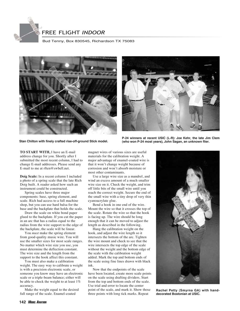
In a recent column I included a photo of a spring scale that the late Rich Doig built. A reader asked how such an instrument could be constructed.
Spring scales have three major components: base, spring element, and scale. Rich had access to a full machine shop, but you can use hard balsa for the base and the backplate that holds the scale.
- Draw the scale on white bond paper glued to the backplate. If you cut the paper in an arc that has a radius equal to the radius from the wire support to the edge of the backplate, the scale will be linear.
- Make the spring element from good-quality music wire. You will use the smaller sizes for most scale ranges. No matter which wire size you use, determine the deflection constant—the wire size and the length from the support to the hook affect this constant.
- Make a calibration weight. The easy way to calibrate a weight is with a precision electronic scale, or someone you know may have an electronic scale or a triple-beam balance; either will be able to check the weight to at least 1% accuracy.
- Make the weight equal to the desired full range of the scale. Enamel-coated magnet wires of various sizes are useful materials for the calibration weight. A major advantage of enamel-coated wire is that it won't change weight because of corrosion and won't absorb moisture or most other contaminants.
- Use a large wire size as a mandrel and wind an excess amount of a much smaller wire size on it. Check the weight and trim off little bits of the small wire until you reach the correct weight. Secure the end of the small wire with a tiny drop of very thin cyanoacrylate glue.
- Bend a hook in one end of the wire. Mount the wire so that it crosses the top of the scale. Rotate the wire so that the hook is facing up. The wire should be long enough that it can be moved to adjust the length as described below.
- Hang the calibration weight on the hook, and adjust the wire length so it intersects the bottom of the arc. Tighten the wire mount and check to see that the wire intersects the top edge of the scale without the weight and the bottom edge of the scale with the calibration weight added. Mark the top and bottom ends of the scale using fine lines drawn with black ink.
- Now that the endpoints of the scale have been located, create more scale points on the scale using drafting dividers. Start from the top and bottom ends of the scale. Use trial and error to locate the center point of the scale, and mark it. Show those three points with long tick marks. Repeat this operation until the scale is divided into 16 sections.
- You can indicate the next divisions—one-eighth, three-eighths, five-eighths, and seven-eighths—with shorter tick marks to make a more readable scale.
- If you have worked carefully with a 0.1-ounce calibration weight, you will be able to resolve 0.00625 ounce. This will be about the best you can do using a spring scale. This is more than adequate for checking rubber motor weights at the flying field.
Flight Trim:
The following paraphrased comments are from the Bong Eagles newsletter, Tales of the Eagles. The discussion was about flight trim on outdoor rubber models, but this commentary can also be applied to trimming indoor rubber models.
- If the center of gravity (CG) is too near the leading edge, the model will take too much up-trim and will tend to loop. It will hang on the propeller in the climb and will have a slow, mushing glide.
- One solution is to move the wing forward to make the model more tail-heavy (rearward CG). The model will have a fast climb, and the power run will end with a flat cruise (no climb).
- For indoor models we can't move the wing since we don't strap the wings on with rubber bands. The solution is to locate the wing as close to the propeller as possible; you can accomplish this one of two ways:
- Build the tailboom and tail surfaces as light as possible so that the CG moves forward.
- Make the motorstick as long as possible (the rules for Pennylane and Limited Pennylane limit the total model length), and then build the horizontal stabilizer as large as possible (up to 50% of the wing area). This allows the CG to be located farther back. The stabilizer's lift will contribute to the total lift supporting the model in flight.
Excerpted from another free-flight club newsletter — the Willamette Modelers Club Inc.'s (in Oregon) WMC Patter — are some tips by Bob Eberle about Catapult Gliders. He wrote this piece for publication in the long-gone New York Indoor Times, edited by Ed Whitten.
- "With two Indoor Catapult Glider classes, you guys can't use the excuse that your arm isn't any good anymore! All you need is a short loop of rubber attached to a handle (consult the AMA rule book for specifications). Hook the rubber to the model, pull back, and let go!
- In the workshop, begin by using a long straightedge to be sure you have no decalage (incidence angle difference between wing and stabilizer). If the decalage isn't zero, rebuild the glider until it is. With positive incidence in the stabilizer (leading edge high), the glider will dive in and possibly break. Negative incidence in the stabilizer will make the glider loop uncontrollably.
- Examine the glider from the front and verify that you have stabilizer tilt to cause the turn you want. Left tilt (right stabilizer tip low) gives left turn; opposite for right turn.
[From personal experience, a right-handed flier — catapult in your left hand and glider in your right hand — will be more comfortable setting up for a left turn in the glide. The glider will probably need to be launched while banked to the right. The resulting launch pattern should be a slight right turn sweeping into the left glide turn. The glider must be launched so this S-turn pattern will miss the building structure, and the launch must have enough energy to reach just below the ceiling.]
- For the first test flights, test-glide the model. Launch the model straight ahead with it banked in the direction of the glide turn. If it dives into the turn, the airplane is trying to turn so tightly that it is trying to roll.
- First, check the stabilizer to be sure it isn't warped or has too much tilt. If neither is true, check to see if the wing is warped or cocked (mounted on the fuselage, not perpendicular to the fuselage centerline).
- If it continues to dive into the turn, add a small amount of weight on the wingtip opposite the turn.
- Once the model is gliding properly, launch it straight ahead with about one-third power from the catapult, keeping the nose level. It should come off the catapult and start into a climb while assuming its own bank, then slow and make a smooth transition into the glide.
- If it loops or dives on a low-power launch, check the decalage again. If it rolls too fast into the turn on the low-power launch, launch with a bank away from the turn. Continue this process until the launch is perfect. Repeat this routine with one-half and three-quarter power launches. As the launch power increases, launch with the nose pointed higher and higher. A full-power launch may well be almost vertical."
High-Power Winding:
No matter what kind of rubber you use, there is a way to get significantly more turns into a motor. (The motor you use must be clean and free from mechanical damage.) The following winding procedure requires a torque meter to guide you as you wind. The torque meter should have a hook that holds one end of the motor, and it should be clearly visible as you apply turns.
- Hook the motor between the torque meter and the winder. Stretch the motor to three or four times the normal loop length. (Measure the length by sliding a short piece of a large drinking straw over the motor so that the loop is squeezed down to a minuscule size.) Lay the motor over a ruler that has a pin to hook the knot end over. The length is the distance from the pin to the end of the loop.
- As you wind, the torque reading will rise slowly until it reaches a plateau that remains almost constant for some time. This plateau corresponds to the cruising portion of the flight. If you happen to see what level of torque the motor needs to fly level, you can tell if this motor will be a match for it. Choose a different motor if necessary.
- As you continue to wind, the torque reading will begin to rise rapidly. Reduce the stretch slightly and watch the torque meter. If the reading drops and then rises as you pull back, continue to wind slowly. Repeat this test often while continuing to wind slowly. When the torque reading doesn't drop as you test, move in until it drops, and then resume winding. At some point the torque reading will begin to rise rapidly. Stop winding! The motor will break if you continue.
- Also, stop winding when you have come in to where the motor length equals the distance between the model's propeller hook and rear hook. It is helpful if you have a stand that holds the winder that same distance from the torque meter. At that time you can massage the knots in the motor. This will cause the torque reading to drop. If that torque will cause the model to climb into the ceiling, back off turns until a better torque level is reached, and massage the knots again.
MA
Transcribed from original scans by AI. Minor OCR errors may remain.

