
FREE FLIGHT SCALE - 2003/07
Author
Fernando Ramos 19361 Mesa Dr., Villa Park CA 92861 E-mail: [email protected]
Every once in awhile a particular technique has to be revisited. For those of you who want to build as light as possible yet maintain structural integrity, this review is for you. Fulton Hungerford, of spokewheel fame, is one of the most clever people I have ever met. He turned the AMA fraternity upside down one year when he competed with a Rubber Scale model in the Power event and won! Nothing in the rule book stated that it couldn't be done.
At another Nationals (Nats) I attended, Fulton entered an F4U Corsair that had a balsa-formed fuselage, and the model flew 35 seconds indoors. In the 1970s this was not the type of model to enter. At that time, 35 seconds was a pretty long flight.
Fulton was on the West Coast for business when the Flightmasters had a speed event for scale racing airplanes. He entered a Loening amphibian biplane. It went straight as a die. Making a scale model fly straight for 80 feet is quite difficult. Fulton won the event, but quite a few people were perturbed since the Loening was not a racing airplane.
I mention all of this not to show that Fulton was a troublemaker, but that he could do things that no one else at the time could do. There still isn't the type of wire wheel available that Fulton used to make. A friend of mine went to visit him years ago, when he and his wife were in Florida. My friend was amazed to see the way Fulton made those wonderful spoke wheels. He had a Rube Goldberg system that would produce the spokes.
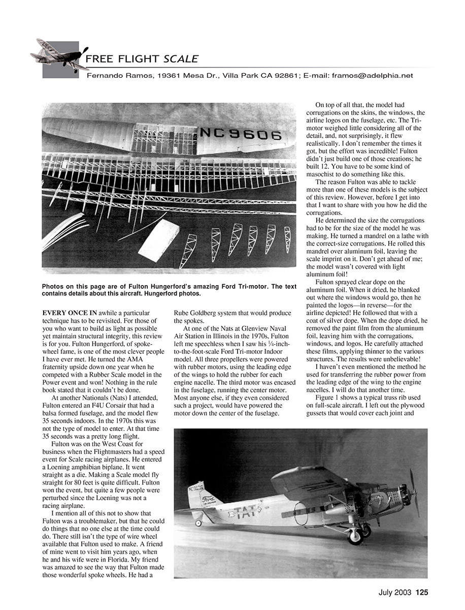
At one of the Nats at Glenview Naval Air Station in Illinois in the 1970s, Fulton left me speechless when I saw his 1/4-inch-to-the-foot-scale Ford Tri-Motor indoor model. All three propellers were powered with rubber motors, using the leading edge of the wings to hold the rubber for each engine nacelle. The third motor was encased in the fuselage, running the center motor. Most anyone else, if they even considered such a project, would have powered the motor down the center of the fuselage.
On top of all that, the model had corrugations on the skins, the windows, the airline logos on the fuselage, etc. The Tri-Motor weighed little considering all of the detail, and, not surprisingly, it flew realistically. I don't remember the times it got, but the effort was incredible! Fulton didn't just build one of those creations; he built twelve. You have to be some kind of masochist to do something like this.
The reason Fulton was able to tackle more than one of these models is the subject of this review. However, before I get into that I want to share with you how he did the corrugations.
He determined the size the corrugations had to be for the size of the model he was making. He turned a mandrel on a lathe with the correct-size corrugations. He rolled this mandrel over aluminum foil, leaving the scale imprint on it. Don't get ahead of me; the model wasn't covered with light aluminum foil!
Fulton sprayed clear dope on the aluminum foil. When it dried, he blanked out where the windows would go, then he painted the logos—in reverse—for the airline depicted. He followed that with a coat of silver dope. When the dope dried, he removed the paint film from the aluminum foil, leaving him with the corrugations, windows, and logos. He carefully attached these films, applying thinner to the various structures. The results were unbelievable!
I haven't even mentioned the method he used for transferring the rubber power from the leading edge of the wing to the engine nacelles. I will do that another time.
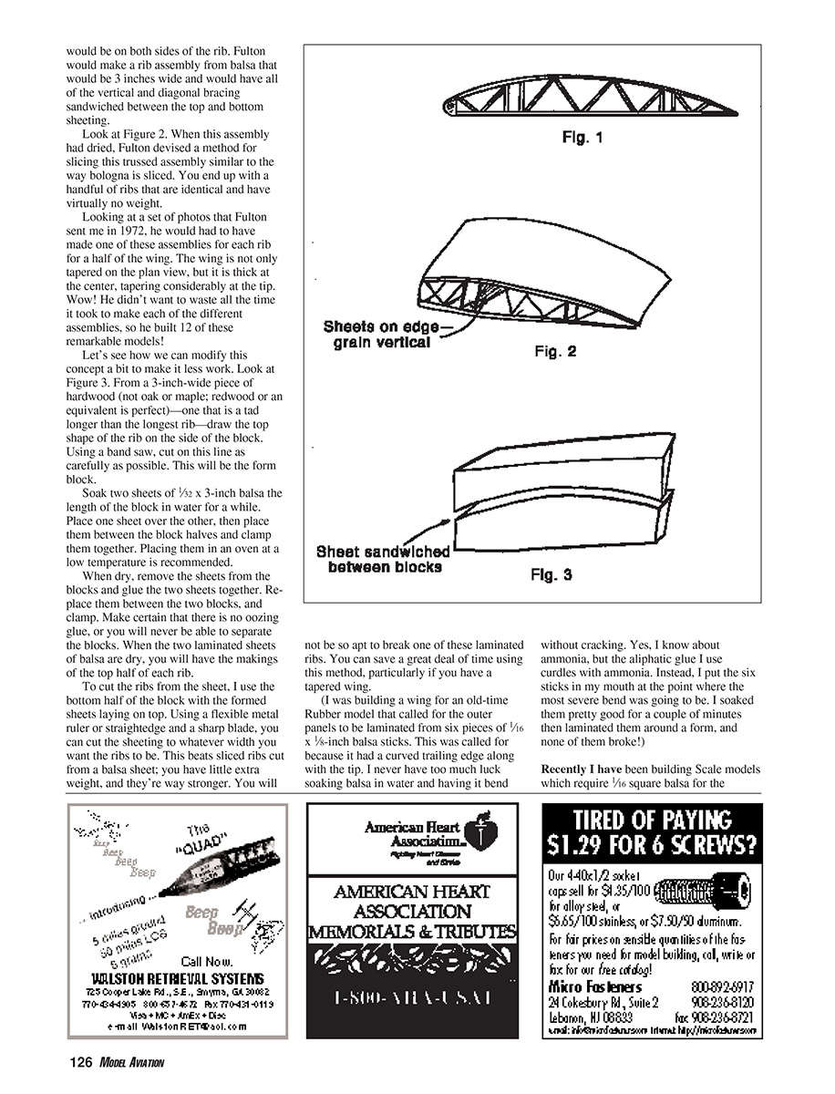
Figure 1 shows a typical truss rib used on full-scale aircraft. I left out the plywood gussets that would cover each joint and would be on both sides of the rib. Fulton would make a rib assembly from balsa that would be 3 inches wide and would have all of the vertical and diagonal bracing sandwiched between the top and bottom sheeting.
Look at Figure 2. When this assembly had dried, Fulton devised a method for slicing this trussed assembly similar to the way bologna is sliced. You end up with a handful of ribs that are identical and have virtually no weight.
Looking at a set of photos that Fulton sent me in 1972, he would have had to make one of these assemblies for each rib for a half of the wing. The wing is not only tapered on the plan view, but it is thick at the center, tapering considerably at the tip. Wow! He didn't want to waste all the time it took to make each of the different assemblies, so he built twelve of these remarkable models.
A modified method for laminated ribs (Figure 3)
Let's see how we can modify this concept a bit to make it less work. From a 3-inch-wide piece of hardwood (not oak or maple; redwood or an equivalent is perfect)—one that is a tad longer than the longest rib—draw the top shape of the rib on the side of the block. Using a band saw, cut on this line as carefully as possible. This will be the form block.
Soak two sheets of 1/32 x 3-inch balsa the length of the block in water for a while. Place one sheet over the other, then place them between the block halves and clamp them together. Placing them in an oven at a low temperature is recommended.
When dry, remove the sheets from the blocks and glue the two sheets together. Replace them between the two blocks, and clamp. Make certain that there is no oozing glue, or you will never be able to separate the blocks. When the two laminated sheets of balsa are dry, you will have the makings of the top half of each rib.
To cut the ribs from the sheet, use the bottom half of the block with the formed sheets laying on top. Using a flexible metal ruler or straightedge and a sharp blade, you can cut the sheeting to whatever width you want the ribs to be. This beats sliced ribs cut from a balsa sheet: you have little extra weight, and they're way stronger. You will not be so apt to break one of these laminated ribs. You can save a great deal of time using this method, particularly if you have a tapered wing.
(I was building a wing for an old-time rubber model that called for the outer panels to be laminated from six pieces of 1/16 x 5-inch balsa sticks. This was called for because it had a curved trailing edge along with the tip. I never have too much luck soaking balsa in water and having it bend without cracking. Yes, I know about ammonia, but the aliphatic glue I use curdles with ammonia. Instead, I put the six sticks in my mouth at the point where the most severe bend was going to be. I soaked them pretty good for a couple of minutes then laminated them around a form, and none of them broke!)
Longerons and bracing
Recently I have been building scale models which require 1/16 square balsa for the longerons. Instead I have opted to use bass or spruce of the same dimension. For the little appreciable weight, the added strength is worth it—especially after the fuselage is covered. I hate to see the fuselage longerons sag between uprights.
I also can't stress enough to use diagonal bracing on the sides, tops, and bottoms of fuselages. If you are building a CO2, electric, or diesel-powered model, diagonal bracing inside the fuselage is also highly recommended. It prevents stabilizer and rudder tilt after the model has been covered. On a CO2 model I use 1/32 square basswood for the internal bracing. It is amazing how these little sticks keep a fuselage from twisting. I use 1/16 square balsa on larger models.
Covering technique: wet tissue wadding
Sometime back I mentioned rolling Japanese tissue into a ball the size of a spitwad. Some of my flying buddies thought I was pulling their legs. The more I do this, the better I like the results. I'll explain the procedure.
After, say, a wing has been coated sufficiently with dope for attaching the tissue, cut a piece of tissue just large enough to cover a lower wing half. Wad up this piece into the smallest ball you can make. Open it up so that it is completely flat, without any hidden folds. You will have plenty of creases.
Spray an even coat of water over the entire dull side of the tissue sheet. Carefully place it on the lower half of the wing. Pull it in all directions until it is pretty smooth. Activate the dope with acetone or MEK (methyl ethyl ketone). When dry, repeat this procedure for the other wing panels. There is little warping, if any.
After each coat of dope I weight down the wing and other parts to dry. The tissue looks as taut as if it had been done without the wadding, with no warps. Some modelers are afraid to apply wet tissue to the model, but using it gives better results. Some of you won't do it any other way but dry, and you still get great results. Whatever works!
A friend of mine is slowly converting from radio control to rubber and CO2, and has no experience in covering with tissue. To prove to him the difference between dry and wet tissue, I covered one side of a fuselage with some curves dry and the other side wet. The difference between the two was night and day. I am not trying to convert some of you die-hards; I just wanted to show you that there is more than one way to get good results.
Kit note
I purchased a Hasegawa kit of the Sopwith Camel. These long-discontinued kits are exceptional—especially mine. I don't have the manual that contains the building sequence, but the plans are there. If someone out there would like to sell me yours (assuming that you have already built the model) or if I may borrow it long enough to copy it, I would greatly appreciate it.
E-mail: [email protected]
Fernando Ramos
Transcribed from original scans by AI. Minor OCR errors may remain.

