
FREE FLIGHT SPORT
Gene Smith, 1401 N. Husband St., Stillwater OK 74075; E-mail: [email protected]
Trimming a free flight model is like working a jigsaw puzzle. Well, it’s sort of like working a jigsaw puzzle if you stretch the analogy almost as far as it can go and still maintain some semblance of a cogent line of reasoning.
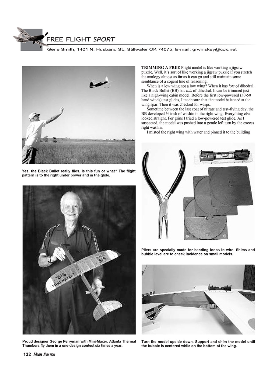
When is a low wing not a low wing? When it has lots of dihedral. The Black Bullet (BB) has lots of dihedral. It can be trimmed just like a high-wing cabin model. Before the first low-powered (30–50 hand winds) test glides, I made sure the model balanced at the wing spar. Then it was checked for warps.
Sometime between the last coat of nitrate dope and test-flying day, the BB developed 1/8 inch of wash-in in the right wing. Everything else looked straight. For grins I tried a low-powered test glide. As I suspected, the model was pushed into a gentle left turn by the excess right wash-in.
I misted the right wing with water and pinned it to the building board with a washout shim. When it was dry, I checked the right wing and found that it had a trace of wash-in remaining. I could live with that. The next low-powered test glide was essentially flat and straight. It was time to head for the flying field.
The first powered flights were made with 200 winds, working up to 500. I used P-30 motors (two loops of 3/16" rubber weighing 10 grams) as the power source. All flights were essentially safe, with the model flying straight ahead. I placed a 1/16-inch balsa shim on the left side of the nose block for right thrust and eventually put 700 winds in the motor. The result was a nice right-climbing circle.
The glide wandered hither and yon, sometimes a little right and sometimes a little left. I wanted to establish a right turn in the glide. The stabilizer could have been tilted to the left, but that would have messed up the DT (dethermalizer) key and would have compromised the airplane’s “good looks.” Some clay on the right wingtip could induce a right turn, but it adds weight and has always been a “trimming method of last resort” for me.
Because of the large amount of dihedral, I figured the rudder could be used for the right turn without causing a problem. Very little rudder extends beyond the narrow slot in the elevator, but I managed to put approximately 1/4 inch of right tab in the last 1/2 inch of the rudder. This did the trick: right turn under power and a nice right turn in the glide.
Why did I decide to use old P-30 motors in the BB? Its weight without the rubber motor was 44 grams. That’s what a somewhat portly P-30 weighs, so I figured that if a 10-gram motor was good enough for a P-30, it was good enough for a BB. I could have used a heavier motor, but that would have required more nose weight, which gets to be a vicious cycle. The added weight of the heavier motor and nose weight increases the wing loading. Therefore, the model has to fly faster and at a more positive angle of attack to generate more lift. That creates more drag. Warps become more effective at the higher airspeed, causing more problems with trimming. I shudder just thinking about it. The 10-gram motor will have to do.
Mini‑Maxer
I have always wanted to build a Mini‑Maxer. The distinctive swept flying surfaces and stabilizer dihedral set the Mini‑Maxer apart from your everyday sport free flight model. The place to which it is set apart is wherever you put all of the late George Perryman’s designs.
All of George’s models have a variation of this distinctive tailplane, and they all seem to fly well. Perhaps it has something to do with George’s success designing models and full‑scale aircraft. Perhaps it is because George was such a true gentleman that his designs don’t dare do anything but behave politely.
Roughly 10 years ago I bought a Sig kit of the Mini‑Maxer. Since then I have opened the box to start construction half a dozen times, only to pick up the die-cut kit wood, estimate its weight, and return the contents to the box and the box to the shelf.
Deciding it was now or never, I made a copy of the kit wood and cut my own parts from light balsa. Any model airplane worth building is worth building light. The time or money you might save by using heavy kit wood is not worth the frustration of trying to get a pig to fly. No offense to the Air Hog lovers in the crowd.
In two months: Adventures in trimming the Mini‑Maxer. Hint: the center of gravity (CG) worked best for me 2-1/4 inches behind the wing’s leading edge—not where it is shown on the plans. Use an 8-inch-diameter propeller for better performance.
When I was deciding what model I wanted to build for this column, I checked to make sure the kit was available to those who might be inspired to try the airplane. Penn Valley Hobby Center has not only the Mini‑Maxer, but most, if not all, of the currently available kits for rubber-powered and gas-engine-powered free flights. Check out www.pennvalleyhobbycenter.com or send $2 for a catalog to Penn Valley Hobby Center, 837 W. Main St., Lansdale PA 19446.
You've Got to Have an Angle:
If your model is going to fly, there has to be an angle between the bottom of the wing and the stabilizer. As I understand it, the term “decalage” refers to the angle between the chord lines of a biplane’s wings. However, many people use the term to refer to the angular difference between the wing chord and stabilizer, and that is how I will use it.
That angle is typically 3° or 4°. If you think all of the plans you see in the magazines and in kits have that angle drawn correctly, there is a bridge in Brooklyn I would like to sell to you.
When I resumed building rubber-powered models, one of my first projects was a cute little No-Cal built from plans in a magazine. It was a low-winger in pre-World War II Army Air Corps colors. I built it according to the plans and did a nice job, considering it was my first such effort since the seventh grade.
When it was time for the first test flight, doink—a nose dive! I gave it another try, and doink! To make a long story shorter, I finally realized that the poor little model had no decalage. Few things are so sad as a free flight model with no decalage.
The stabilizer was on the bottom of the fuselage, and it took roughly 1/4 inch of shims between the fuselage and the leading edge of the stabilizer to get the model to fly. The model flew great with the proper decalage. The plans showed no decalage. So always check the decalage shown on the plans and double-check the decalage on the finished model before the first test flight.
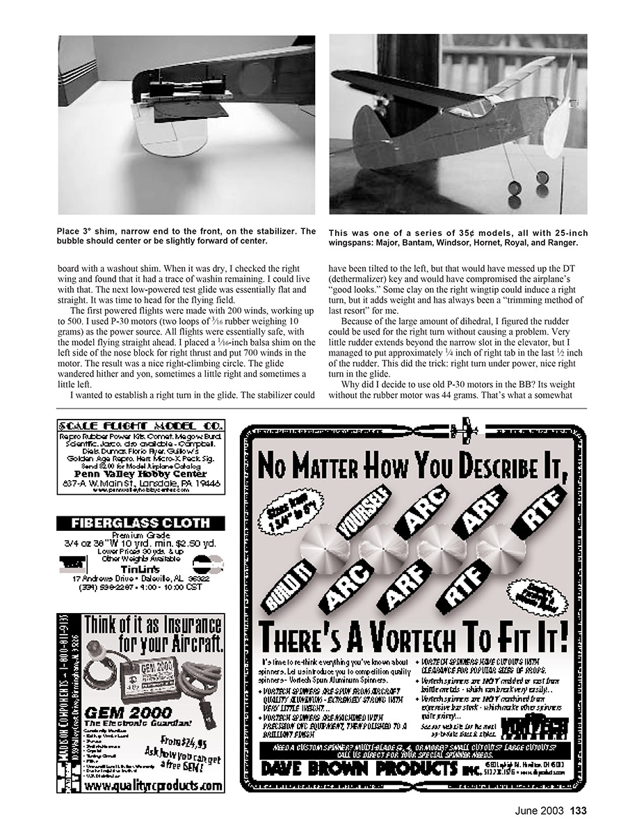
There are some neat commercial products available for checking RC models’ decalage, but they are too heavy for most rubber-powered aircraft. I have seen plans for a slick, build-it-yourself, miniature decalage checker; I may build one someday, but for now I use a simple method that requires little in the way of construction or materials.
You will need the following:
- Ernst Products plastic wedges (three shims: 1°, 2°, and 3°; mine are 2-1/2 inches square)
- a bubble level glued to a small balsa base
Steps:
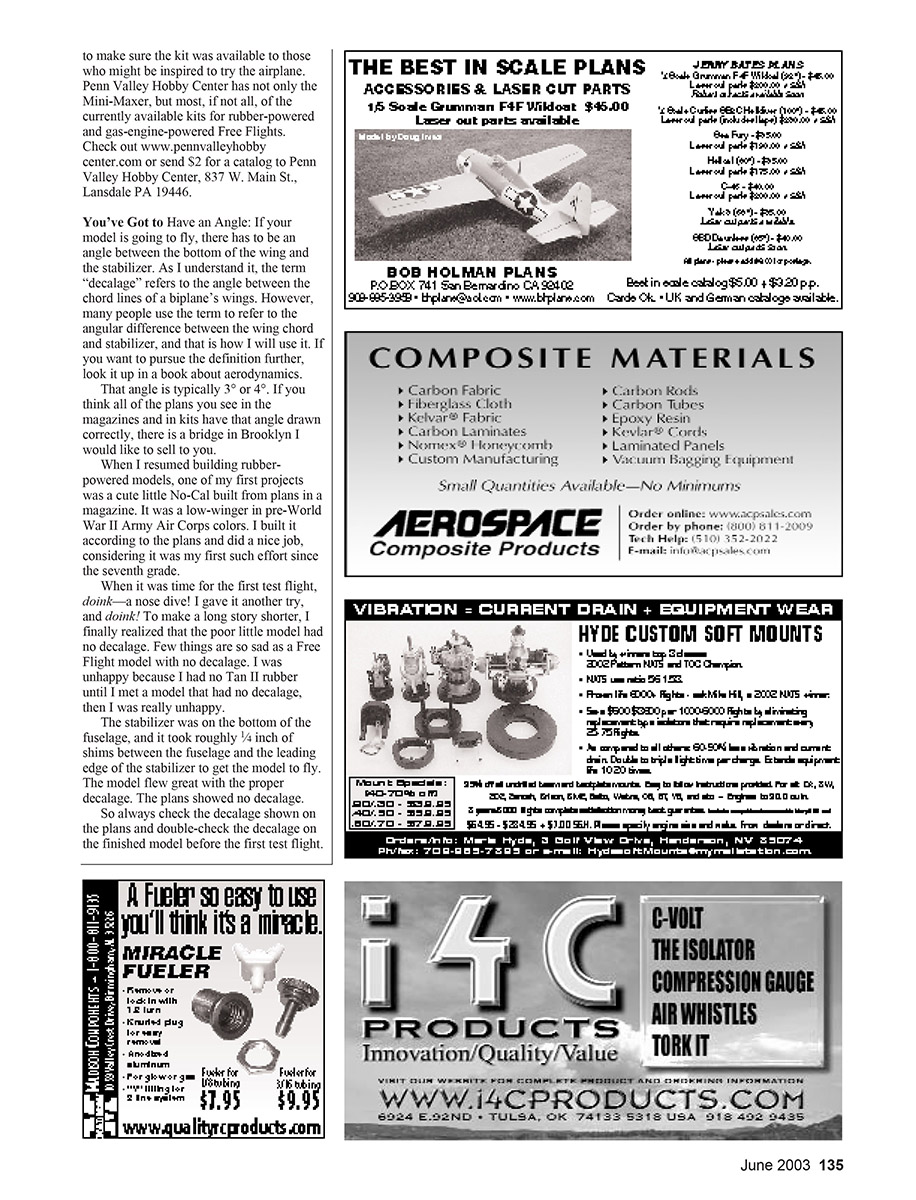
- Assemble the model, turn it upside down, and place the bubble level on the bottom of the wing.
- Support the tail and shim it until the bubble is level on the bottom of the wing.
- Put the 3° wedge on the bottom of the stabilizer with the thick end of the wedge to the rear.
- Move the level to the wedge on the stabilizer. The bubble should be near level.
- If the decalage is off, shim the front or rear of the stabilizer until you have it close.
This is a good starting point for those first test glides. If the model’s wing has no upsweep to the leading edge and a small stabilizer, it may require more negative in the stabilizer. If your local hobby shop can’t get the Ernst shims, try Sheldon's Hobbies at www.sheldonshobbies.com.
I Think I'm in Love: What kind of pliers do you use to bend loops in music wire?
Round-nose, of course. I have a relatively inexpensive pair of round-nose pliers I have been using in my shop for the last 10 or so years. After those years of use and abuse they have lost some of their temper, and it has become a contest between which will bend first: the pliers or the wire.
I saw a pair of pliers in a fish-tackle catalog. They had one jaw that was round and the other concave. They cost $28.99, but I took the plunge and am really happy. These pliers make bending loops a breeze.
Transcribed from original scans by AI. Minor OCR errors may remain.

