
FREE FLIGHT SPORT and SCALE - 2001/03
Author
Fernando Ramos 19361 Mesa Dr., Villa Park CA 92861 E-mail: [email protected]
Since returning from my wonderful trip to the United Kingdom, I have been very busy building models in between finishing the Cub wings.
I was corrected: the Cub does not have a Clark Y airfoil, as I stated in the last column; it has the USA 356. I am not familiar with this airfoil, except that it is supposed to have a bit of undercamber.
Those of you who know me realize I cannot build one airplane at a time; I have at least 10 going at any given point. I go from one to another, enjoying the construction of each model. Often one will give a temporary headache when a hurdle comes up. It is good for me to leave the problem and approach it later, when a solution is reached.
Common plans errors
I wrote an earlier column regarding the many areas on plans where errors can be located. With all the building I have been doing in the last couple months, I can't believe how many mistakes I have encountered. No matter how great the plans look, each set has its share of inaccuracies.
I am not mentioning this to put blame on the individuals who drew up the plans—heaven knows I can't draw plans worth a hoot. I just want you to be aware so you don't have to redo something, or even give up on a model. I'll review a few major areas where errors tend to crop up.
- Wing cradle vs. actual airfoil: On a low-wing model, there is usually a cradle where the wing sets. If you cut the airfoil in the cradle using the drawing shown on the fuselage profile, you may find the built wing (made from the airfoil drawing) won't fit the cradle. I learned to use the airfoil parts that were removed from the cradle for the root part of the wing. This assures that the wing will fit correctly.
- Stabilizer width mismatch: For some reason, the width of the stabilizer shown on the side view never seems to correspond with the stabilizer drawing. I have encountered this many times. By being aware of this, I can adjust the fuselage structure to ensure that the stabilizer will set properly on the fuselage.
- Bulkhead asymmetry: Full-size fuselage bulkhead drawings are also an area of concern; one side rarely matches the other side. Sometimes the error is subtle and doesn't show up until stringers are being installed. To eliminate this, draw half the bulkhead onto a folded piece of paper. Position the fold on the centerline of the bulkhead on the drawing. When the paper is unfolded, the result is an accurate and symmetrical bulkhead.
- Wing halves: Even though wing halves are shown on the plans, I usually use one depicted half to build both wings. I spray WD-40 on the drawing and let it soak through, then wipe off the excess with a paper towel. This allows the wing drawing to be seen on the back side of the plan, producing a mirror image of the wing half. The WD-40 will evaporate long after the wing has been constructed, returning the plan to its original state.
There are many more possible plan errors, but these are some of the more common ones.
Covering: tissue followed by silk
How many of you have covered a model with Japanese tissue followed by silk? I'll bet many of you.
What is the advantage of doing so? It makes doping the silk much easier, and it takes much less dope to do it this way. Doping silk is a rather time-consuming procedure, since silk is a porous material. If you hurry the doping, you will have a real mess on your hands; it can ooze through and glob on the back side, making a mess of the silking.
At the British Nationals, I asked Terry Manley (well-known Free Flight and Radio Control Scale modeler) how he covered his very large Blackburn Torpedo biplane. (He worked at Blackburn for 40 years.) The model had an eight- or nine-foot wingspan.
I couldn't believe it when he told me he used tissue and silk! There had to be a small fortune in all that silk. Terry irons the silk, then he applies it to the doped tissue using wallpaper paste. Yes—wallpaper paste. He dabs the paste through the silk until there is total adhesion. His comment is that it looks awful until the paste dries.
The paste is mostly water, and the surface would be ready for doping after the water has evaporated.
I will try this method and pass on what I experience. I will compare weights using this system to others, to see if there is an advantage.
Derek Knight's letter and number templates
From the fertile mind of Derek Knight comes a nifty idea.
When Derek is ready to cut letters or numbers from tissue, he makes templates from 1/16" plywood first. This thin wood is easy to cut with scissors. He uses an X-Acto knife to cut out the centers of the letters and/or numbers.
This technique makes cutting the letters much easier. I saw Derek do it with very small characters. You can use these templates repeatedly.
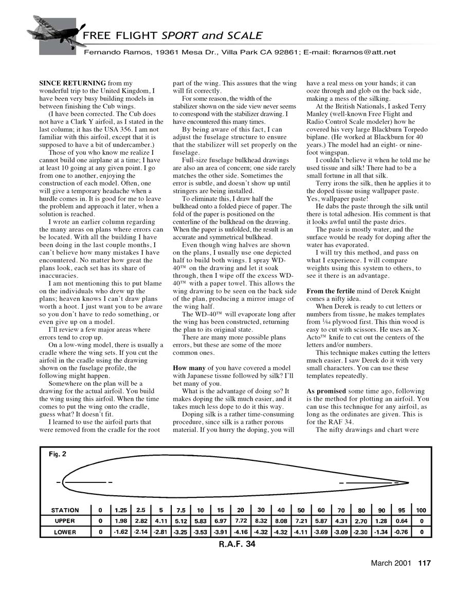
Plotting an airfoil (example: RAF 34)
As promised some time ago, following is the method for plotting an airfoil. You can use this technique for any airfoil, as long as the ordinates are given. This example is for the RAF 34.
The drawings and chart were done for me by my good friend, Blair Reardon.
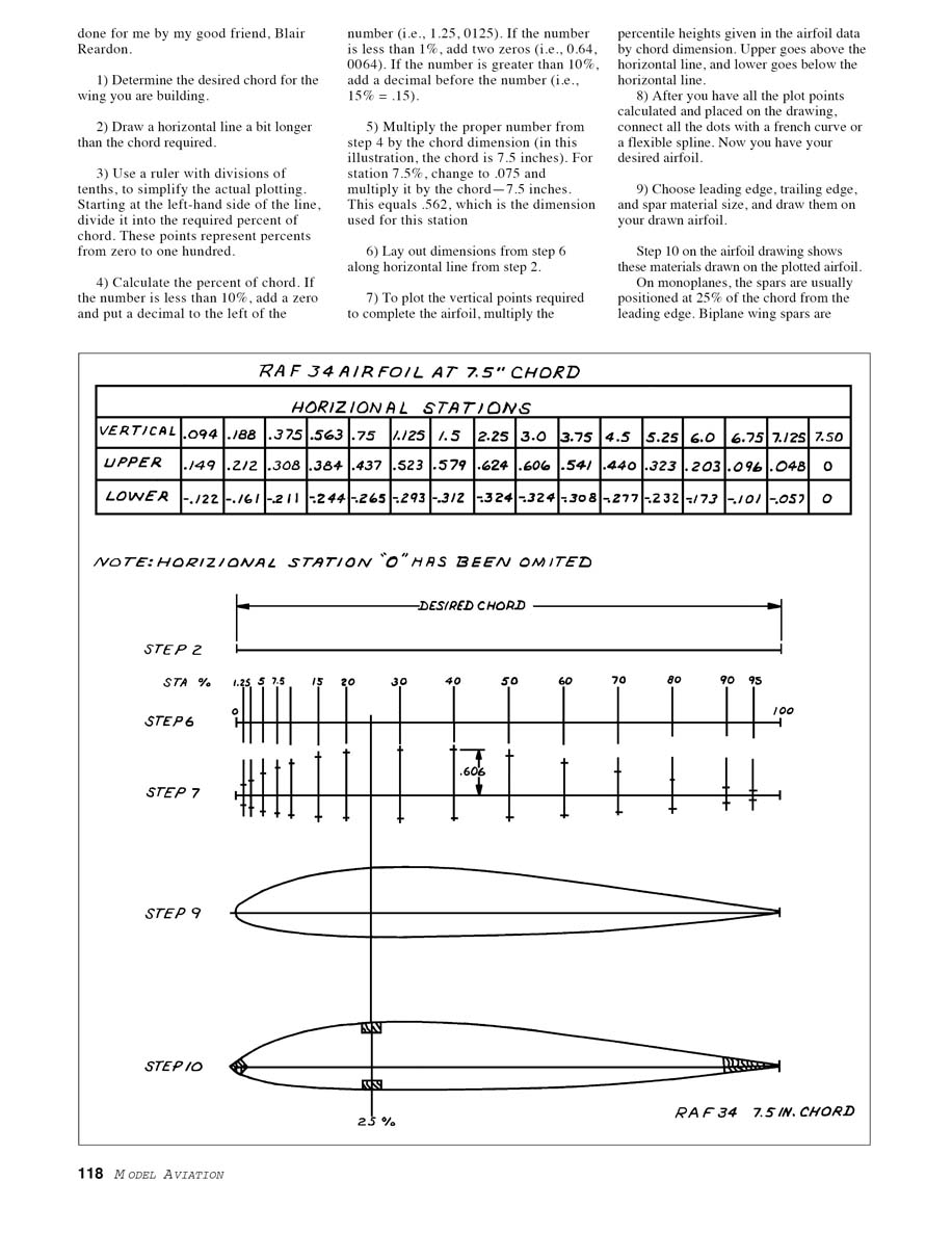
- Determine the desired chord for the wing you are building.
- Draw a horizontal line a bit longer than the chord required.
- Use a ruler with divisions of tenths, to simplify the actual plotting. Starting at the left-hand side of the line, divide it into the required percent-of-chord stations. These points represent percents from zero to one hundred.
- Convert percent values to decimal fractions for calculation. Examples:
- 1.25% = 0.0125
- 0.64% = 0.0064
- 15% = 0.15
- Multiply the proper decimal by the chord dimension. For example, for a chord of 7.5 inches and station 7.5%: use 0.075 × 7.5 = 0.562 inches. This is the horizontal distance from the leading edge for that station.
- Lay out the horizontal dimensions from step 5 along the horizontal line from step 2.
- To plot the vertical points required to complete the airfoil, multiply the percentile heights given in the airfoil data by the chord dimension. Plot upper-surface points above the horizontal line and lower-surface points below it.
- After you have all the plot points calculated and placed on the drawing, connect the dots with a French curve or a flexible spline. Now you have your desired airfoil.
- Choose leading edge, trailing edge, and spar material sizes, and draw them on your plotted airfoil.
- On monoplanes, spars are usually positioned at 25% of the chord from the leading edge. On biplanes, wing spars are positioned to attach to cabane and interplane struts.
I hope this information is not too complicated to follow.
Resources
Dan and Kerin Galloway of Flying Scale report that this plans company is still in business. You might remember that Dan's father, Bill Galloway, drew up incredibly detailed plans of more than 30 airplanes from World War I, the Golden Age, and World War II. Some show retracts that work and an array of details that can make a winner from any of these exquisite plan drawings.
Bill passed away approximately eight years ago, and Dan and his wife have continued with the business. However, the new neighbors didn't want to be helpful when Dan's mother sold her house, so any mail they received regarding the business went astray.
To get a plans listing, send an SASE to:
- Flying Scale
19008 Colony Rd. Metairie, LA 70003
You won't regret it.
You can purchase a great video of the Flying Aces Club Nationals Mark XII (2000) from Jim Cagle. He has five formats:
- VHS (regular) — $30
- S-VHS (super VHS) — $35
- 8mm — $30
- Hi-8 — $35
- mini-DV digital — $40
This high-quality video is professionally done. Jim's address is:
- Jim Cagle
648 Andover Village Pl. Lexington, KY 40509
Include $4.95 for shipping and handling.
Transcribed from original scans by AI. Minor OCR errors may remain.

