
Frequently Asked Questions - 2004/06
By Bob Aberle
E-mail: [email protected]
This is the second monthly FAQ column in which I try to answer, as clearly as possible, questions you have written or e-mailed to me. Each question is given a sequential number for identification purposes. Because publication space is somewhat limited, part of each column will be in the magazine, and the published portion and spillover material will be posted on the AMA web site. Let's start!
Q15 — Spar taper on Scratch One
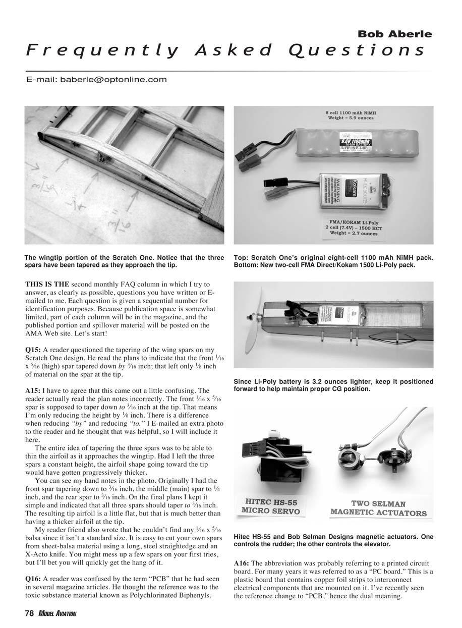
A reader questioned the tapering of the wing spars on my Scratch One design. He read the plans to indicate that the front 1/16" x 5/16" (high) spar tapered down by 3/16"; that left only 1/8" of material on the spar at the tip.
I agree this wording was confusing. The reader read the plan notes incorrectly. The front 1/16" x 5/16" spar is supposed to taper down to 3/16" at the tip — that means the height is reduced by 1/8". There is a difference between reducing "by" and reducing "to." I e-mailed an extra photo to the reader and he found that helpful, so I will include it with the plans.
The whole idea of tapering the three spars was to thin the airfoil as it approaches the wingtip. If the three spars had remained constant in height, the airfoil toward the tip would have become progressively thicker. My original hand notes indicated the following tapers:
- front spar to 3/16"
- middle (main) spar to 1/4"
- rear spar to 3/16"
On the final plans I simplified this to indicate that all three spars taper to 3/16". The resulting tip airfoil is a little flat, but that is preferable to having a thicker airfoil at the tip.
If you can't find 1/16" x 5/16" balsa (it's not a standard size), it's easy to cut your own spars from sheet balsa using a long steel straightedge and an X-Acto knife. You might ruin a few on the first tries, but you'll quickly get the hang of it.
Q16 — What does "PCB" mean?
A reader was confused by the term "PCB" and thought it referred to the toxic material polychlorinated biphenyls.
In the context of radio control and electronics articles, PCB almost always means printed circuit board. It was commonly called a "PC board" for many years — a plastic board with copper foil strips to interconnect electrical components. Recently you’ll see the abbreviation written as "PCB," which can create the dual-meaning confusion.
Q17 — Can I convert Scratch One to Lithium-Polymer batteries?
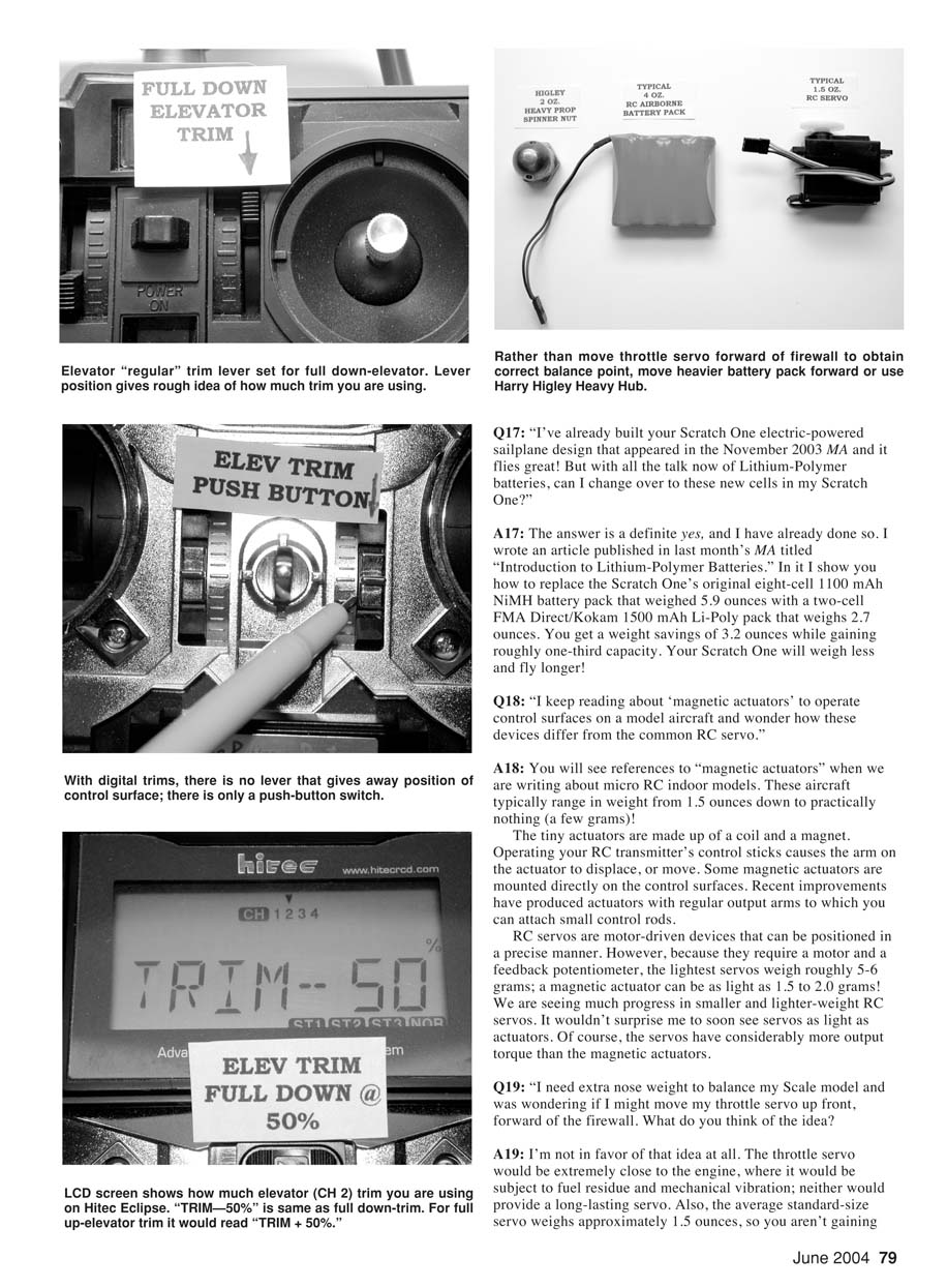
Yes. I’ve already done it. In last month's MA I wrote an article titled "Introduction to Lithium-Polymer Batteries." In it I show how to replace the Scratch One's original eight-cell 1100 mAh NiMH battery pack (weighing 5.9 ounces) with a two-cell FMA Direct/Kokam 1500 mAh Li-Poly pack (weighing 2.7 ounces). You get about a 3.2-ounce weight savings and roughly one-third more capacity. Your Scratch One will weigh less and fly longer.
Q18 — What are magnetic actuators and how do they differ from RC servos?
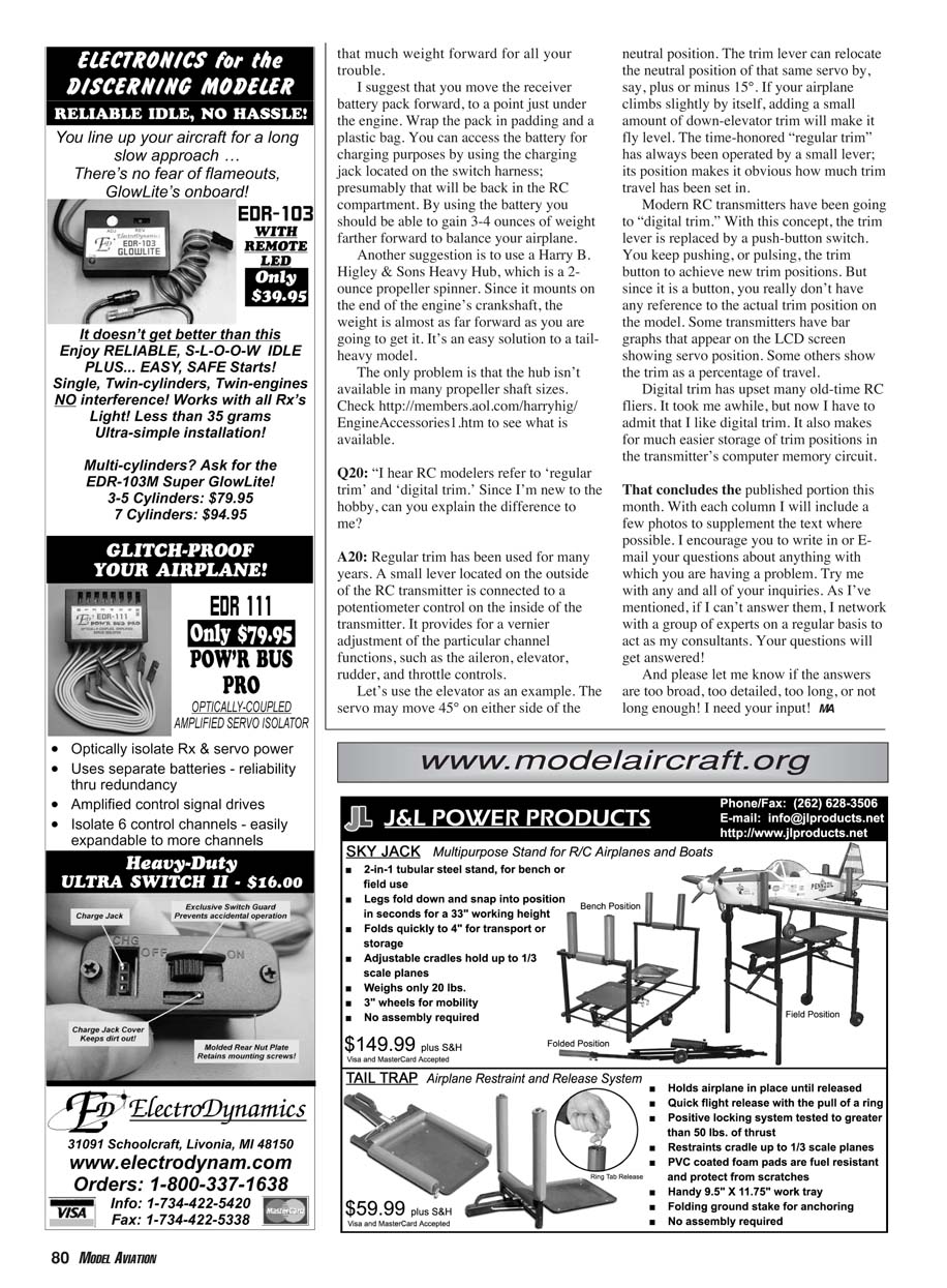
You’ll see references to "magnetic actuators" mainly in micro RC indoor model discussions. These aircraft typically weigh from about 1.5 ounces down to only a few grams.
Magnetic actuators are tiny devices made of a coil and a magnet. Operating your transmitter's control sticks causes the actuator arm to displace. Some are mounted directly on control surfaces; recent improvements have produced actuators with small output arms for attaching control rods.
RC servos are motor-driven devices with feedback potentiometers and are positioned precisely. Because servos require a motor and potentiometer, the lightest servos weigh roughly 5–6 grams; magnetic actuators can weigh as little as 1.5–2.0 grams. Progress in miniaturizing servos continues, and I wouldn’t be surprised to see servos reach actuator-like weights soon. Servos do, however, provide considerably more output torque than magnetic actuators.
Q19 — Moving the throttle servo forward for nose weight
I don't recommend moving the throttle servo forward (in front of the firewall) to add nose weight. The servo would be very close to the engine, exposed to fuel residue and heavy vibration — not a recipe for long servo life. Also, a standard-size servo weighs only about 1.5 ounces, so you won't gain much weight in the nose.
Instead, try these options:
- Move the receiver battery pack forward to a point just under the engine. Wrap the pack in padding and a plastic bag. You can access the battery for charging via the charging jack on the switch harness, which should remain in the RC compartment. This can move 3–4 ounces farther forward to help balance the airplane.
- Use a Harry B. Higley & Sons Heavy Hub (a 2-ounce propeller spinner). It mounts on the end of the engine crankshaft, placing weight almost as far forward as you can get it and is an easy solution for a tail-heavy model.
Note: The heavy hub isn't available in all propeller shaft sizes. Check the manufacturer's listings (for example, http://members.aol.com/harryhig/EngineAccessories1.htm) to see availability.
Q20 — Regular trim vs. digital trim
Regular trim has been used for many years. A small lever on the outside of the transmitter operates a potentiometer inside; it provides vernier adjustment for channels (ailerons, elevator, rudder, throttle). For example, if a servo moves 45° each side of neutral, the trim lever might relocate neutral by ±15°. The lever's position makes it obvious how much trim is set.
Digital trim replaces the lever with push-button switches. You pulse the button to change trim positions, but because it's a button you don't have a tactile reference to the trim position. Some transmitters show trim positions on an LCD bar graph or as a percentage. Digital trim upset many long-time fliers at first, but I now like it. It also makes it easier to store trim positions in a transmitter's memory.
That concludes the published portion this month. With each column I’ll include a few photos to supplement the text where possible. I encourage you to write or e-mail your questions about anything you’re having a problem with. If I can’t answer them I network with a group of experts who act as consultants. Your questions will get answered!
Please let me know if the answers are too broad, too detailed, too long, or not long enough — I need your input!
Transcribed from original scans by AI. Minor OCR errors may remain.

