
Frequently Asked Questions - 2004/08
Bob Aberle E-mail: [email protected]
This is the fourth monthly column in which I provide the best possible answers to questions readers have written or e-mailed to me. Each set of questions and answers is given a sequential number for identification purposes. Because publication space is limited, the questions featured here and any spillover material will be posted on the AMA Web site.
Q31: "I have seen references to RC transmitters that operate on Mode II and Mode I. What are they referring to?"
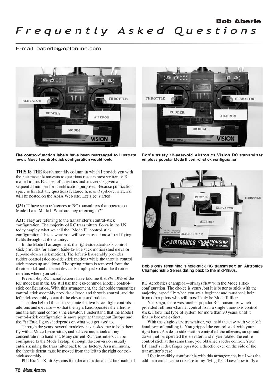
They are referring to the transmitter's control-stick configuration. The majority of RC transmitters flown in the U.S. today employ what we call the "Mode II" control-stick configuration. This is what you will see in use at most local flying fields throughout the country.
Mode II arrangement:
- Right-side, dual-axis control stick provides:
- Aileron (side-to-side stick motion)
- Elevator (up-and-down stick motion)
- Left stick assembly provides:
- Rudder control (side-to-side stick motion)
- Throttle control (up-and-down stick motion)
- The throttle stick spring return is removed and a detent device is used so the throttle remains where you set it.
Present-day RC manufacturers estimate that 8–10% of RC modelers in the U.S. still use the less-common Mode I control-stick configuration. With Mode I:
- Right-side stick provides aileron and throttle control
- Left-side stick controls elevator and rudder
The idea behind Mode I is to separate the two basic flight controls—ailerons and elevator—so that the right hand operates the ailerons and the left hand controls the elevator. Mode I is more popular throughout Europe and the Far East. Many current RC transmitters can be configured to Mode I, although conversion usually entails sending the transmitter back to the factory; at minimum, the throttle detent must be moved from the left to the right control-stick assembly.
Phil Kraft—Kraft Systems founder and national and international RC Aerobatics champion—always flew with the Mode I stick configuration. The choice is yours, but it's better to stick with the majority, especially when you are a beginner and must seek help from other pilots who will most likely be Mode II fliers.
Years ago there was another popular RC transmitter that provided full four-channel control from a single three-axis control stick. I flew that type for more than 20 years until it finally became extinct. With the single-stick transmitter:
- You held the case with your left hand, cradling it.
- You gripped the control stick with your right hand.
- Side-to-side motion controlled the ailerons.
- Up-and-down motion operated the elevator.
- Rotating the entire control stick provided rudder control.
- Your left hand's index finger operated a throttle lever on the side of the transmitter's case.
I felt comfortable with this arrangement, but I was the odd man out since no one else at my flying field knew how to fly a single-stick transmitter. The single-stick transmitter’s popularity diminished and its complicated control stick raised prices. I still own an Airtronics single-stick transmitter but seldom use it anymore.
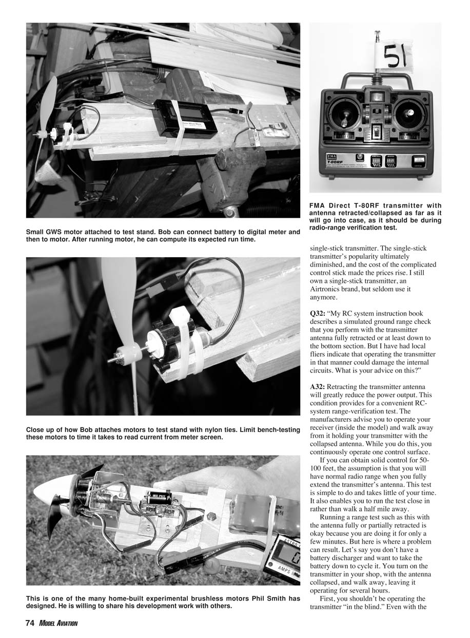
Q32: "My RC system instruction book describes a simulated ground range check that you perform with the transmitter antenna fully retracted or at least down to the bottom section. But I have had local fliers indicate that operating the transmitter in that manner could damage the internal circuits. What is your advice on this?"
Retracting the transmitter antenna will greatly reduce the power output. This condition provides a convenient RC-system range-verification test. Manufacturers advise you to operate your receiver (inside the model) and walk away from it holding your transmitter with the collapsed antenna while continuously operating one control surface.
If you can obtain solid control for 50–100 feet, the assumption is that you will have normal radio range when you fully extend the transmitter’s antenna. This test is simple, quick, and lets you perform the check close in rather than walking far away.
However, do not run the transmitter with the antenna fully or partially retracted for long periods. Reasons:
- Even with the antenna collapsed, the transmitter is still broadcasting a signal; you shouldn't be operating it "in the blind."
- With the antenna collapsed the transmitter output circuit is out of tune. The output current can increase substantially and the output-stage transistor(s) can easily burn out.
Conclusion: Only operate your RC transmitter with the antenna collapsed for a short range-check period.
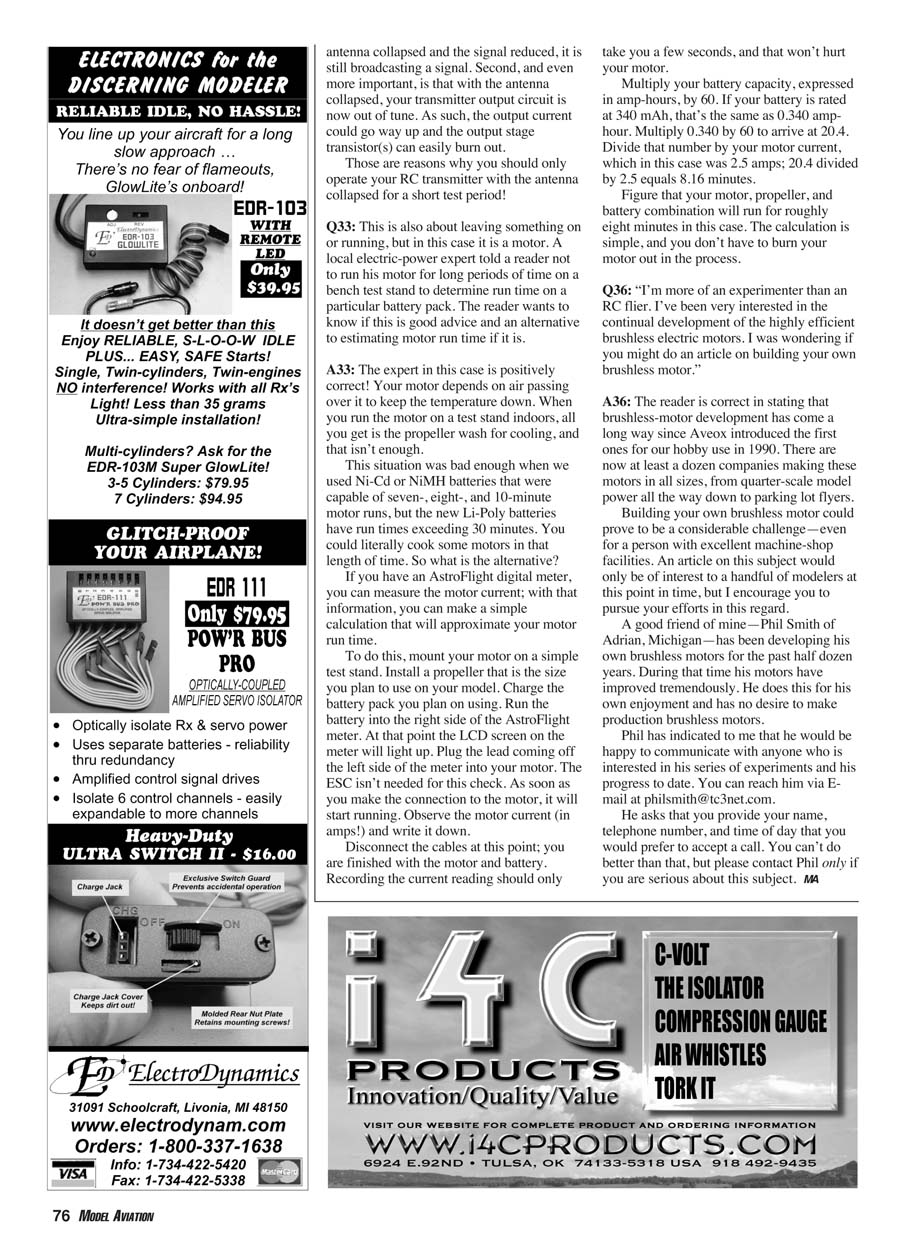
Q33: "This is also about leaving something on or running, but in this case it is a motor. A local electric-power expert told a reader not to run his motor for long periods of time on a bench test stand to determine run time on a particular battery pack. Is this good advice and what is an alternative to estimating motor run time?"
The expert is correct. Your motor depends on air passing over it to keep its temperature down. When you run the motor on a test stand indoors, you only get the propeller wash for cooling, and that isn't enough.
This was a concern even with Ni-Cd or NiMH batteries with 7–10 minute runs, but the new Li-Poly batteries can give run times exceeding 30 minutes. You could literally cook some motors in that length of time.
Alternative method to estimate run time using an AstroFlight digital meter:
- Mount your motor on a simple test stand and install the propeller size you plan to use on the model.
- Charge the battery pack you plan to use.
- Run the battery into the right side of the AstroFlight meter; the LCD will light up.
- Plug the lead from the left side of the meter into your motor (ESC not needed for this check). The motor will start running.
- Observe and record the motor current in amps. Recording the current only takes a few seconds and won't harm the motor.
- Calculate estimated run time:
- Convert battery capacity to amp-hours (e.g., 340 mAh = 0.340 Ah).
- Multiply amp-hours by 60 to get minute-capacity (0.340 × 60 = 20.4).
- Divide that number by the motor current in amps (e.g., 20.4 ÷ 2.5 A = 8.16 minutes).
This gives a rough estimate of motor run time for your motor/propeller/battery combination without risking overheating the motor.
Q36: "I'm more of an experimenter than an RC flier. I've been very interested in the continual development of the highly efficient brushless electric motors. I was wondering if you might do an article on building your own brushless motor."
Brushless-motor development has come a long way since Aveox introduced the first hobby motors in 1990. There are now at least a dozen companies making these motors in sizes from parking-lot flyers up to quarter-scale model power.
Building your own brushless motor can be a considerable challenge, even with excellent machine-shop facilities. An article on the subject would interest only a handful of modelers at this time, but I encourage you to pursue it if you're serious.
A friend, Phil Smith of Adrian, Michigan, has been developing his own brushless motors for the past half dozen years and his designs have improved tremendously. He does this for his own enjoyment and has no desire to produce them commercially.
If you're interested in communicating with Phil, you can reach him via e-mail at [email protected]. He asks that you provide your name, telephone number, and the time of day you prefer to accept a call. Please contact Phil only if you are serious about this subject.
MA
Transcribed from original scans by AI. Minor OCR errors may remain.

