
Frequently Asked Questions
Bob Aberle
E-mail: [email protected]
This is the seventh monthly column in which I try to give you the best possible answers to questions you have written in or sent via E-mail. I expect to make this introduction only one more time. By now you should be familiar with the routine.
Each new question is given a sequential number for identification purposes. Because publication space is limited, part of this column will be printed here, and the whole thing will be posted on the AMA Web site at http://modelaircraft.org/mag/FAQ/index.asp. All questions and answers appear there.
Let's start!
Q54
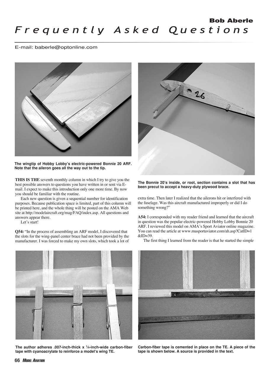
"In the process of assembling an ARF model, I discovered that the slots for the wing-panel center brace had not been provided by the manufacturer. I was forced to make my own slots, which took a lot of extra time. Then later I realized that the ailerons hit or interfered with the fuselage. Was this aircraft manufactured improperly or did I do something wrong?"
A54
I corresponded with my reader and learned that the aircraft in question was the popular electric-powered Hobby Lobby Bonnie 20 ARF. I reviewed this model on AMA’s Sport Aviator online magazine. You can read the article at www.masportaviator.com/ah.asp?CatID=1&ID=39.
The first thing I learned from the reader is that he started the simple assembly process before he had read one word of the provided instructions. The first thing he did was apply molded-plastic covers at each wingtip. Then he proceeded to join the two wing panels using a plywood brace that fits into a slot cut out in the center section. His trouble began when he couldn't find any slots for the plywood brace. Thinking that the manufacturer had forgotten this step and wanting to get on with the assembly, he routed out two new slots and joined and cemented the wing panels.
The next problem was that when he placed the assembled wing on top of the fuselage, the ailerons touched the fuselage sides and were restricted in motion because they interfered with the fuselage.
It didn't take long to figure out the problem. He had placed those molded-plastic wingtips on the center section. It was easy to do since the wing panels are rectangular in shape. These tips quickly covered the slots that the manufacturer had provided for the plywood brace. So the tips were at the center, and the center portion was at the tips; both wing panels had been reversed. The ailerons were designed to start approximately 4 inches out from the centerline and then run out to the tips. With the panels reversed, the ailerons went almost to the centerline of the fuselage, which is why they were hitting the fuselage.
The reader corrected the aileron-clearance problem and ultimately finished the aircraft. But the real story here is that the reader did not go through the instructions before starting the assembly process. If he had attempted to join the wing panels before adding the molded-plastic tips, his error would quickly have been discovered. You have to ask yourself, "If I have to do a great deal of complicated cutting to an ARF, am I doing something wrong?" Even an ARF, which requires little assembly time, can be put together improperly if you fail to read the provided instructions.
Q55
"I have noted that the rubber bands used to hold the wing to my model's fuselage are beginning to cut into the wing trailing-edge material. Is there an easy way to reinforce this area so that the rubber bands don't eventually cut through the trailing edge?"
A55
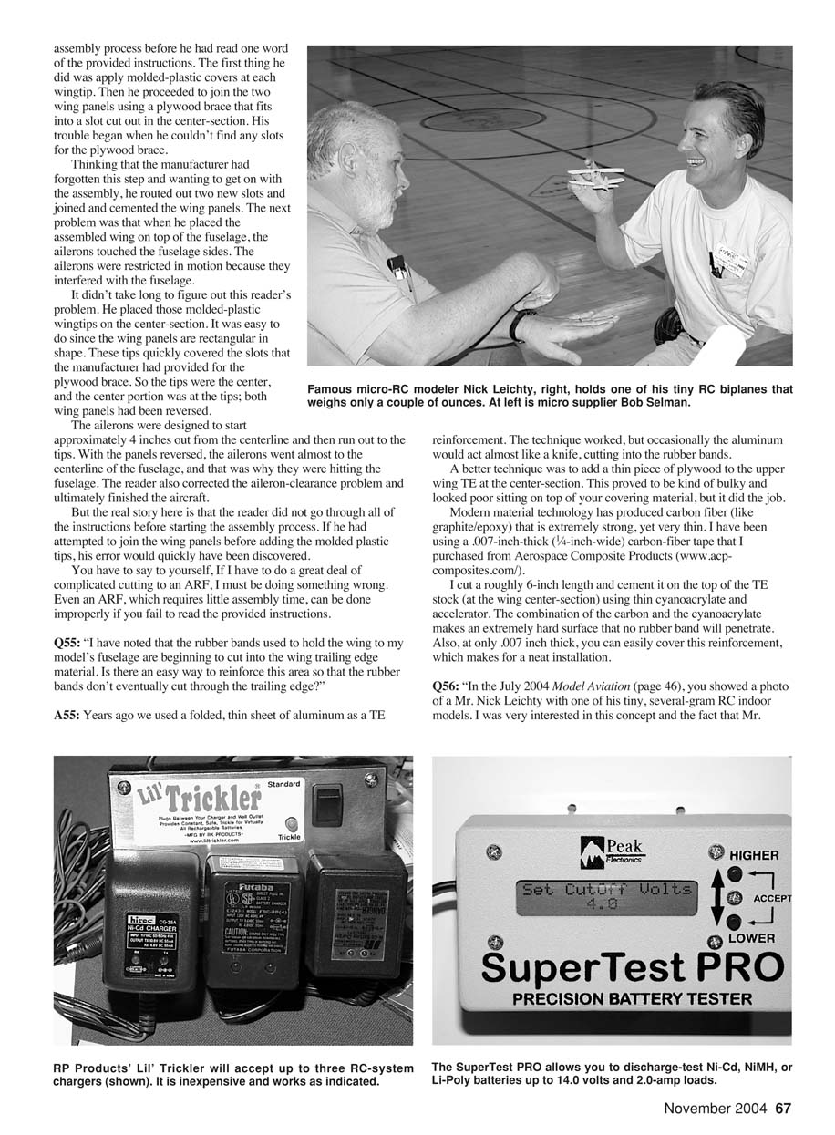
Years ago we used a folded, thin sheet of aluminum as a trailing-edge (TE) reinforcement. The technique worked, but occasionally the aluminum would act almost like a knife and cut into the rubber bands.
A better technique was to add a thin piece of plywood to the upper wing TE at the center section. This proved to be bulky and looked poor sitting on top of the covering material, but it did the job.
Modern materials technology has produced carbon fiber (graphite/epoxy) that is extremely strong yet very thin. I have been using a 0.007-inch-thick, 1/4-inch-wide carbon-fiber tape purchased from Aerospace Composite Products (www.acp-composites.com).
I cut a roughly 6-inch length and cement it on the top of the TE stock at the wing center section using thin cyanoacrylate and accelerator. The combination of the carbon and the cyanoacrylate makes an extremely hard surface that no rubber band will penetrate. Also, at only 0.007 inch thick, you can easily cover this reinforcement, which makes for a neat installation.
Q56
"In the July 2004 Model Aviation (page 46), you showed a photo of a Mr. Nick Leichty with one of his tiny, several-gram RC indoor models. I was very interested in this concept and the fact that Mr. Leichty lives only about an hour from me. Do you have any more information on him, or can you tell me where to find sources for these tiny airplanes?"
A56
My apologies for that omission. Nick has a complete catalog of his ultra-micro RC components and accessories. Most are custom-built or handmade for this application. Nick resides in Florida. You can E-mail him at [email protected] or call him at (941) 377-9808.
September 17–19, Nick and many other indoor RC specialists participated in the micro-flyers seminars held during the Northeast Electric Aircraft Technology Fair in Downsville, New York. You can obtain more details about this gathering and seminar at www.neafair.org.
Q57
"I recently read about using a 24-hour appliance timer to operate a power strip, to which I can plug in a series of RC-system chargers. The idea is to set the timer to come on for something like one hour in each 24-hour period. This effectively provides a trickle charge on the batteries. Is that a good idea?
"I also have a question on battery cycling. I'm on a low budget so I'm not ready to buy a fancy device to discharge my batteries. What kind of an inexpensive load can I use to discharge-test my batteries? How low should I allow the voltage to go during a test discharge?"
A57
I've heard of that 24-hour timer technique for many years. The idea is to leave the chargers on just long enough, in a 24-hour period, to maintain a full charge level. The trick is knowing exactly how much time to leave the chargers on. Many would debate whether it should be one, two, or three hours in a 24-hour period. I doubt if any two people could agree on the exact "on" period.
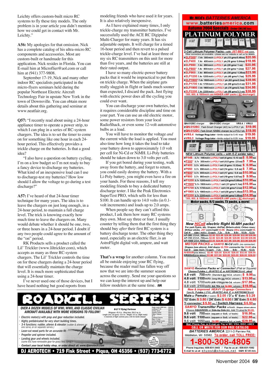
RK Products sells a product called the Lil' Trickler (www.liltrickler.com), which accepts as many as three RC-system chargers. The Lil' Trickler controls the time for these chargers during a 24-hour period so they essentially maintain the charge level. It is much more sophisticated than using a simple 24-hour timer and is relatively inexpensive. I have heard nothing but good reports from modeling friends who have used it for years.
As I have explained many times, I only trickle-charge my transmitter batteries. I've successfully used the ACE RC Digipulse Multi-Charger for many years. It has six adjustable outputs. It will charge for a timed 16-hour period and then revert to a pulsed trickle-charge level. I've had at least three of my six RC transmitters on this unit for more than five years, and the batteries are still at their rated output.
I have so many electric-power flight packs that it would be impractical to put them all on trickle charge. When an airplane gets really sluggish in flight or lands much sooner than expected, I discard the pack. Just flying with electric power provides plenty of cycling.
You can discharge-test your own batteries, but it requires discipline and time. You can use:
- An old electric motor,
- Power resistors from an electronics supplier,
- 12-volt automotive bulbs as a load.
You will have to monitor the voltage and the current while the load is applied. You must also time how long it takes the load to take your battery down to approximately:
- 1.0 volt per cell for Ni-Cd or NiMH cells,
- 3.0 volts per cell for Li-Poly cells.
If you walk away and forget to return during a discharge test, you could easily destroy the battery. With a Li-Poly battery, you might even have a fire. For these reasons, I tell my modeling friends to buy a dedicated battery discharge tester. I like the Peak Electronics SuperTester Pro, which sells for less than $100. It can handle up to 14.0 volts (in 0.1-volt increments) and loads up to 2.0 amps.
When people say they can't afford this product, I ask them how many RC systems they own. Most say three or four. I usually counter by telling them that the first thing they should buy after their first RC system is a battery discharge tester. The other essential item, especially as an electric flier, is an AstroFlight digital volt, ampere, and watt meter.
That's a wrap for another column. You must all be outside enjoying your RC flying, because the reader mail has fallen way off now that we are into the summer season across the country. Send me your questions so we can keep the interest up and help our fellow modelers at the same time.
MA
Transcribed from original scans by AI. Minor OCR errors may remain.

