
Frequently Asked Questions - 2005/04
Bob Aberle
E-mail: [email protected]
THIS IS THE 13th monthly column in which I try to give you the best possible answers to questions you have written in or E-mailed to me. Each question is given a sequential number for identification purposes.
Because publication space is limited, part of these monthly columns appear here, and the columns in their entirety are posted on the MA Web site at www.modelaircraft.org/mag/faq/index.asp. Questions there are arranged by category, which helps you retrieve data for particular subjects. When you call up a question, it reads "Answer ..." at the end. Double-click on that word, and the answer, along with any related photos, will be displayed.
Let's start!
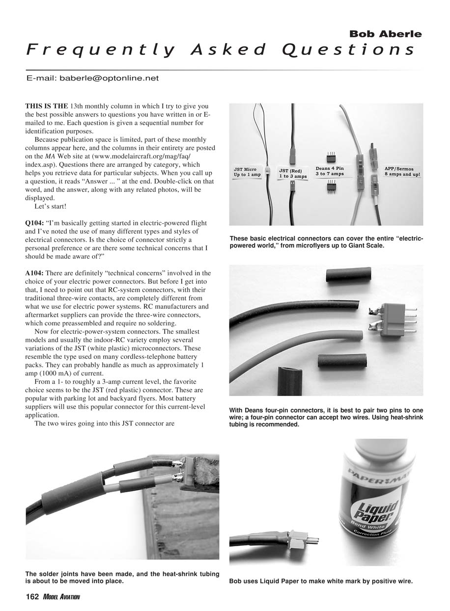
Q104: "I'm basically getting started in electric-powered flight and I've noted the use of many different types and styles of electrical connectors. Is the choice of connector strictly a personal preference or are there some technical concerns that I should be made aware of?"
A104
There are definitely technical concerns involved in the choice of your electric power connectors. RC-system connectors, with their traditional three-wire contacts, are completely different from what we use for electric power systems. RC manufacturers and aftermarket suppliers can provide the three-wire connectors, which come preassembled and require no soldering.
Connector types and typical current ranges:
- JST (white plastic microconnectors)
- Used on the smallest models and indoor-RC variety.
- Resemble connectors used on many cordless-telephone battery packs.
- Suitable for roughly up to 1 amp (1000 mA).
- JST (red plastic)
- Common from about 1 to roughly 3 amps (popular with parking-lot and backyard flyers).
- Supplied preassembled with two pigtail lead wires already attached (you splice into the existing wiring; cover splices with heat-shrink tubing).
- Some suppliers attempt to extend use to ~8 amps — avoid this. Red JST gets hot around 4 A and may melt by 6–7 A. Recommended limit: 3 A maximum, 2 A is safer.
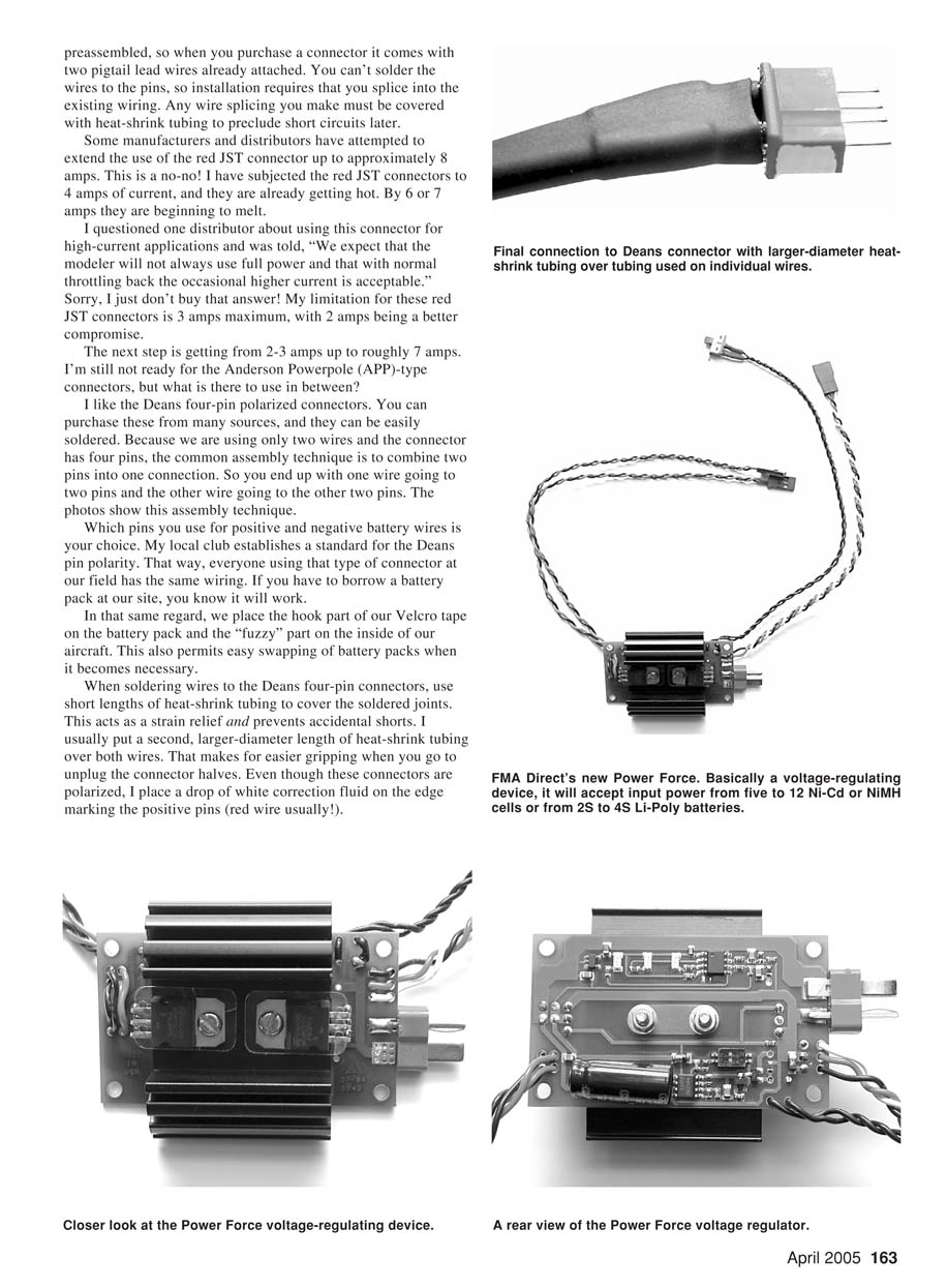
- Deans four-pin polarized connectors
- Good for the range between about 3 and 7 amps.
- Connector has four pins; common assembly technique is to combine two pins per wire (one wire to two pins, the other wire to the other two pins).
- Pins are easily soldered. Use short lengths of heat-shrink tubing over solder joints for strain relief and to prevent shorts; then a second larger-diameter heat-shrink over both wires to make unplugging easier.
- Establishing a standard pin polarity at your flying field is useful so batteries are interchangeable. Mark the positive edge (I put a drop of white correction fluid on the positive side).
- We place the Velcro hook side on the battery pack and the fuzzy side inside the aircraft to permit easy swapping.
- Anderson Powerpole (APP) connectors (also known as Sermos connectors)
- Suitable from roughly 8 amps and up; generally appropriate for Speed 400 motor applications and larger.
- Wires to APP pins can be soldered or mechanically crimped using a special tool. Soldering can be tricky; crimp tools make the job reliable.
- I recommend a good crimping tool; Anderson makes an expensive one, and West Mountain Radio sells a PWRcrimp tool for about $49.95 (see www.westmountainradio.com/PWRcrimp.htm).
Other connectors on the market include Deans Ultra and AstroFlight Zero Loss.
Wire gauge considerations
- Selecting the right connector is only part of the equation — use wire of sufficient gauge for the current you expect. Connector pins may survive but thin wire can overheat and fail.
- Wire is generally stranded and referred to by American Wire Gauge (AWG). Typical recommendations:
- Up to 1 amp (JST white micro): AWG 22
- 1 to 3 amps (red JST): AWG 18
- 3 to 7 amps (Deans four-pin): AWG 18
- 8 to 15 amps (APP): AWG 16
- 15 to 30 amps: AWG 14
- 30 to 60 amps: AWG 12
Final notes
- Use stranded wire (not solid) for aircraft.
- Cover all splices and solder joints with heat-shrink tubing for insulation and strain relief.
- Be conservative with connector and wire choices; overheating and melting are real risks if you exceed a component’s practical current handling.
- My apologies for the length, but these are important safety and performance concerns.
---
Q105: "I'm contemplating my first large-scale model aircraft. My initial plans indicate the need for at least 10 servos. I've been doing a lot of reading on this subject and have determined that I must be very conscious of my current drain from my airborne battery pack. I also gather that my choice of wiring must also be able to support the higher current levels.
Should I just be considering higher capacity batteries and heavier gage wire, or is there something on the market that can help me with my new aircraft project?"
A105
I am not a Giant Scale or quarter-scale specialist, but I did make inquiries and learned the following:
- Practical experience
- Giant-scale models commonly use larger-capacity batteries and heavy-duty extension cables supplied by RC-system manufacturers.
- Modelers who fly giant 3-D-type models (hovering and lots of vertical performance) often use redundant battery packs, redundant receivers, and extra-heavy-gauge wiring.
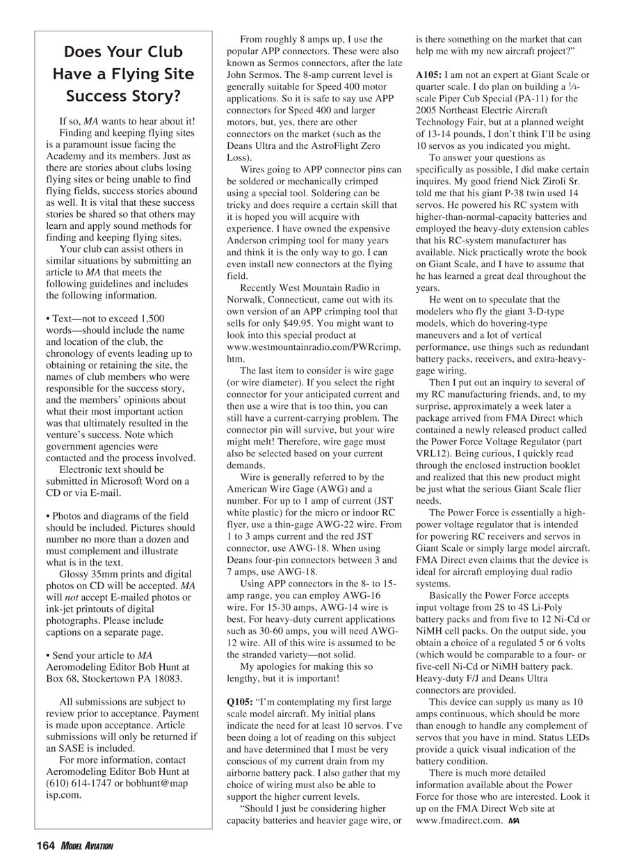
- Product recommendation: Power Force Voltage Regulator (FMA Direct, part VRL12)
- The Power Force is a high-power voltage regulator intended to provide regulated power to receivers and servos in Giant Scale or other large models. FMA Direct says it’s suitable for aircraft using dual radio systems.
- Inputs: 2S to 4S LiPo packs or 5 to 12 NiCd/NiMH cells.
- Outputs: regulated 5 V or 6 V (comparable to four- or five-cell NiCd/NiMH battery packs).
- Connectors: heavy-duty F/J and Deans Ultra connectors provided.
- Capacity: up to 10 amps continuous (should handle many servo complements).
- Status LEDs give a quick visual indication of battery condition.
- More information is available from FMA Direct: www.fmadirect.com.
Transcribed from original scans by AI. Minor OCR errors may remain.

