

Frequently Asked Questions - 2006/06
Bob Aberle | [email protected]
The new JR synthesized RF module
Also included in this column:
- The RAM2 onboard altimeter
- Heat-shrink tubing as strain relief
- Manila-folder plans–parts templates
- Polyspan from Larry Davison
This is the 28th monthly column in which you write or E-mail your questions to me and I try to give you the best possible answers. Each new question is given a sequential number for identification purposes.
Until now part of this column was published in MA and additional questions and answers were posted in a section of the AMA Web site. That Web site is in the process of being revised, and no new postings will be made in the foreseeable future. Therefore, what you read here each month is all you will see. I will advise you when we are able to return to the original format. Recognize that the original "search process" by categories will also be suspended until the full posting is back online. In the meantime, I'm available to help you locate specific subjects of interest; just drop me an E-mail. Also, please keep sending in your questions. That's the only way I can continue to provide this service to all our readers.
Q228
"I noticed that Horizon Hobby is now advertising a new transmitter synthesized RF module which will allow me to select any one of the 50 RC aircraft channels between 72 and 73 MHz. Have you seen or tried one of these new modules? Any comments on the application? Does it function any different than any of the other modules now on the market?"
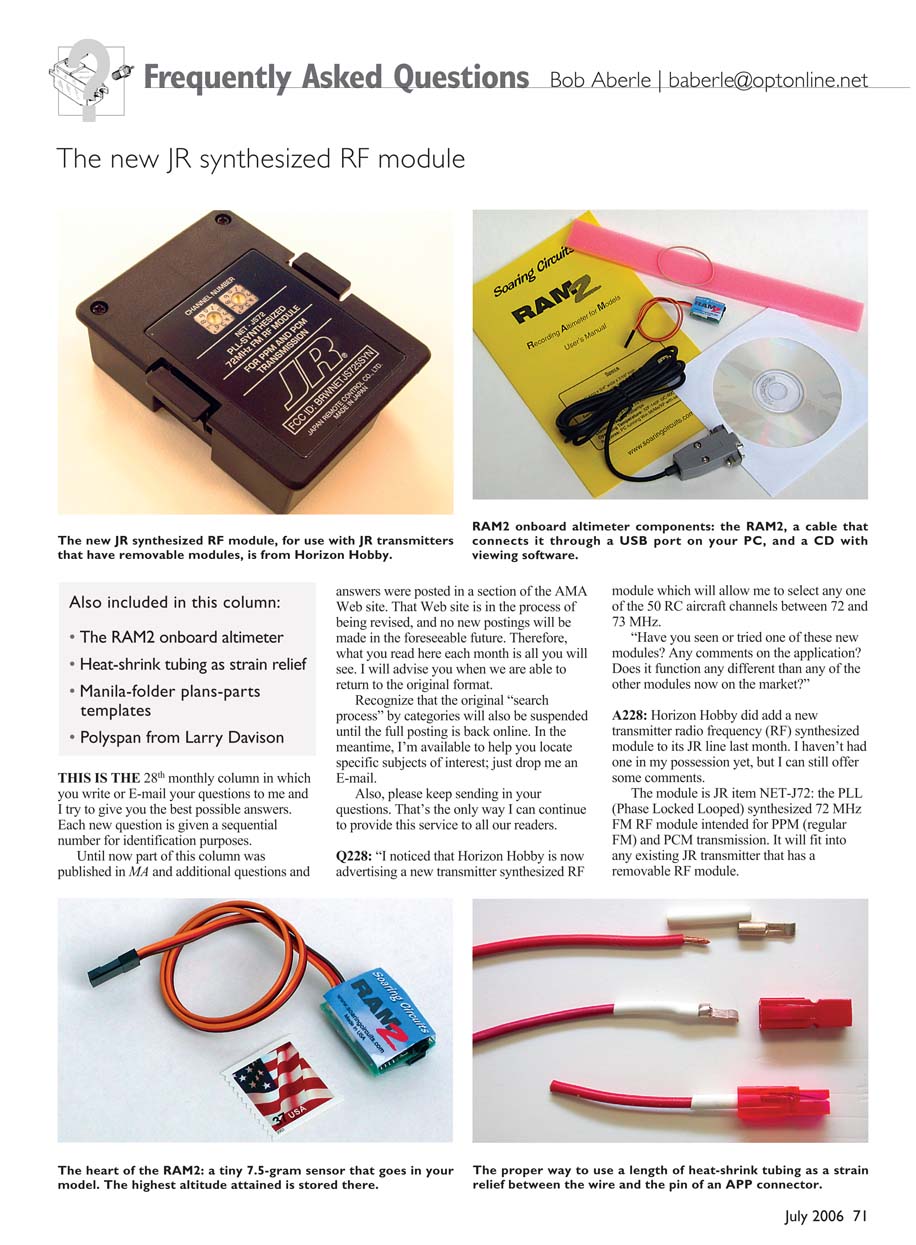
A228: Horizon Hobby did add a new transmitter radio frequency (RF) synthesized module to its JR line last month. I haven't had one in my possession yet, but I can still offer some comments. The module is JR item NET-J72: the PLL (Phase Locked Loop) synthesized 72 MHz FM RF module intended for PPM (regular FM) and PCM transmission. It will fit into any existing JR transmitter that has a removable RF module.
If your JR transmitter doesn't have a removable RF module, you can't use this new synthesized module. Two dials are used to set the 72–73 MHz RC channel numbers from 11 to 60. You set the left-side dial to the first channel digit and the right dial to the second digit. The two dials are located on the outside (outward facing) of the module, so when it is plugged into the transmitter you can still see what channel you are set to. You can also make channel changes without physically removing the module. That is certainly a plus.
You can obtain price and ordering information for this new product by contacting Horizon Hobby at 4105 Fieldstone Rd., Champaign, IL 61822; Tel.: (217) 352-1913; Web site: www.horizonhobby.com.
Q229
"Years ago I saw a wristwatch device that actually measured the maximum altitude attained by your model aircraft in flight. This watch was set to zero and then placed inside the model. It was somewhat difficult to both set and to read after the flight. It was also on the bulky side.
I'd like to learn the altitude of some of my RC sailplanes and was wondering if there are any improved products today that can perform the same function."
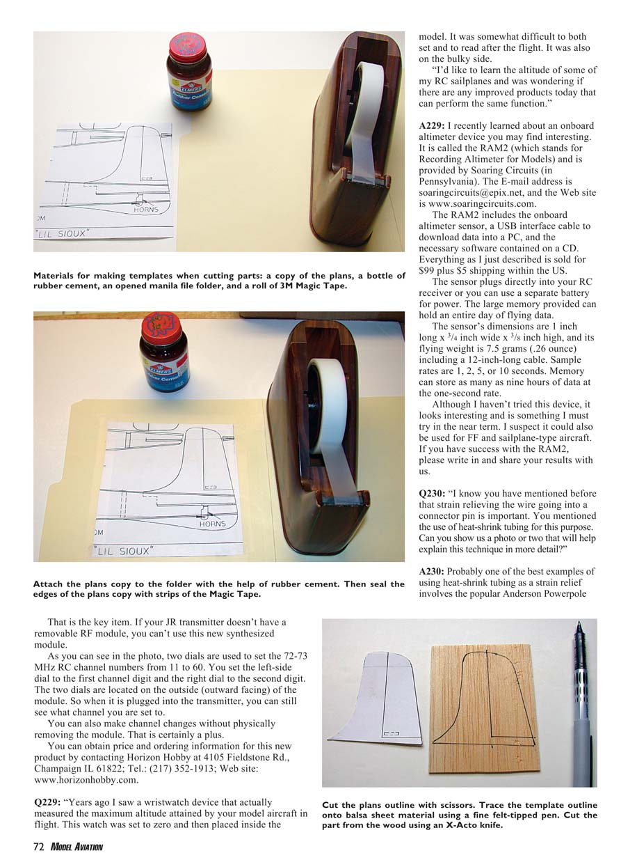
A229: I recently learned about an onboard altimeter device you may find interesting. It is called the RAM2 (Recording Altimeter for Models) and is produced by Soaring Circuits (in Pennsylvania). The E-mail address is [email protected], and the Web site is www.soaringcircuits.com.
The RAM2 includes the onboard altimeter sensor, a USB interface cable to download data into a PC, and the necessary software contained on a CD. Everything as I just described is sold for $99 plus $5 shipping within the US.
The sensor plugs directly into your RC receiver or you can use a separate battery for power. The large memory provided can hold an entire day of flying data.
The sensor's dimensions are 1 inch long × 3/4 inch wide × 3/8 inch high, and its flying weight is 7.5 grams (0.26 ounce) including a 12-inch-long cable. Sample rates are 1, 2, 5, or 10 seconds. Memory can store as many as nine hours of data at the one-second rate.
Although I haven't tried this device, it looks interesting and is something I must try in the near term. I suspect it could also be used for free flight (FF) and sailplane-type aircraft. If you have success with the RAM2, please write in and share your results with us.
Q230
"I know you have mentioned before that strain relieving the wire going into a connector pin is important. You mentioned the use of heat-shrink tubing for this purpose. Can you show us a photo or two that will help explain this technique in more detail?"
A230: Probably one of the best examples of using heat-shrink tubing as a strain relief involves the popular Anderson Powerpole (APP) connector pins. These have also been known throughout the years as the "Sermos" connectors, after the late John Sermos.
Before the mechanical crimping tools became popular, the wire going into the APP connector pin was soldered in place. The job was tedious. In most cases the solder would tend to "wick" back up under the wire insulation. At this junction (wire to connector pin) the solder produced a brittle joint. Flexing of the wire quickly led to its breaking off at the pin.
To relieve the strain at this semi-rigid point of contact, many of us found that a short length of heat-shrink tubing would protect the wire-to-pin joint. To do this right:
- Cut a 1-inch length of heat-shrink tubing and slip it onto the wire.
- Solder or crimp the wire into the connector pin.
- Slide the heat-shrink tubing up over the joint (onto the pin).
- Use a heat gun to shrink the tubing so that it is snug up against the connector pin.
- Insert the pin (with the wire) into the APP plastic housing.
The length of tubing that sticks out beyond the housing will act as an excellent strain relief. Any addition of heat-shrink tubing to a wire/connector joint can add considerably to the overall strength and service life of that joint.
Q231
"I read in many of your construction articles how you fashion templates to cut out parts using unfolded manila file folders. I have a good idea how you do this but would really appreciate a few photos to illustrate your technique."
A231: Start by making a copy of your full-size plans. Roughly cut out the parts you want to fabricate. Paste those portions of the plans to the opened manila folder with rubber cement and then seal the edges with 3M Magic Tape.
Allow that to dry for a couple of hours and then cut to the plan outline with a pair of scissors. Trace the template outline directly onto your balsa or plywood material using a felt-tipped pen (I use the fine-tipped Uni-Ball Vision). When finished, save all your templates in a file folder in case replacement parts are required later.
Q232
"My FF friends use a covering product known as Polyspan. I'd like to try this on some of my park flyers and micro-size aircraft. Where can I learn more about this product?"
A232: Polyspan is a product offered by Society of Antique Modelers Champ Larry Davison. It comes in 10 × 39‑inch sheets for $15 apiece. Larry offers detailed application instructions for this product. You can E-mail him for a copy at [email protected].
MA
Transcribed from original scans by AI. Minor OCR errors may remain.

