
Frequently Asked Questions
Bob Aberle | [email protected]
Q333: Differential motor steering
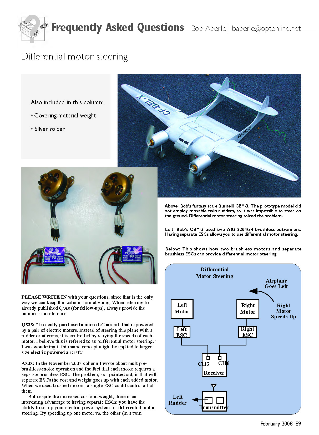
Q333: “I recently purchased a micro RC aircraft that is powered by a pair of electric motors. Instead of steering this plane with a rudder or ailerons, it is controlled by varying the speeds of each motor. I believe this is referred to as ‘differential motor steering.’ I was wondering if this same concept might be applied to larger size electric powered aircraft.”
A333: In the November 2007 column I wrote about multiple-brushless-motor operation and the fact that each motor requires a separate brushless ESC. The problem, as I pointed out, is that with separate ESCs the cost and weight go up with each added motor. When we used brushed motors, a single ESC could control all of them.
Despite the increased cost and weight, there is an interesting advantage to having separate ESCs: you have the ability to set up your electric power system for differential motor steering. By speeding up one motor vs. the other (in a twin configuration), the model can be steered on the ground and, to a degree, in the air as if it had articulated rudder(s). The model I showed in the November column was my new Burnelli CBY-3 “Loadmaster” lifting-body transport. To keep the design simple I did not resort to rudder control (only ailerons and elevator). Hooking up twin operating rudders can pose problems. Unfortunately, this particular lifting-body design proved hard to grip when hand launching the model. Without rudders there was no way to steer a straight course on the ground for takeoff. I did some checking and took an idea from my flying partner, Tom (Mr. NEAT Fair) Hunt. This scheme is generally not mentioned in RC-system handbooks or operating manuals.
Requirements and cautions:
- You will need a programmable RC transmitter and a six-channel-capable receiver. A five-channel receiver will not fit this application and, in fact, could be dangerous depending on where your retract switch was set. (Editor’s note: Channel 5 isn’t proportional on all radio systems and/or its switch can’t be deactivated.)
- You must have a separate ESC for each of the two brushless motors (which should always be the case).
Receiver/ESC hookup:
- Plug the ESC for the left-side motor (looking from the rear of the model forward) into receiver port No. 3.
- Plug the ESC for the right-side motor into receiver port No. 6.
Example setup (Polk’s Tracker III transmitter):
- PMIX 1: set CH 3 as Master, CH 6 as Slave, mix = +100%.
- This ties the two motors together under normal throttle control so both motors run together.
- PMIX 2: set CH 4 as Master, CH 3 as Slave, mix = +30%.
- PMIX 3: set CH 4 as Master, CH 6 as Slave, mix = −30%.
Notes on mixing:
- It is most important that you limit PMIX 2 and PMIX 3 to ±30% and make sure one is positive while the other is negative. If the motors work opposite to what you expect, reverse the signs or swap channels 3 and 6 at the receiver.
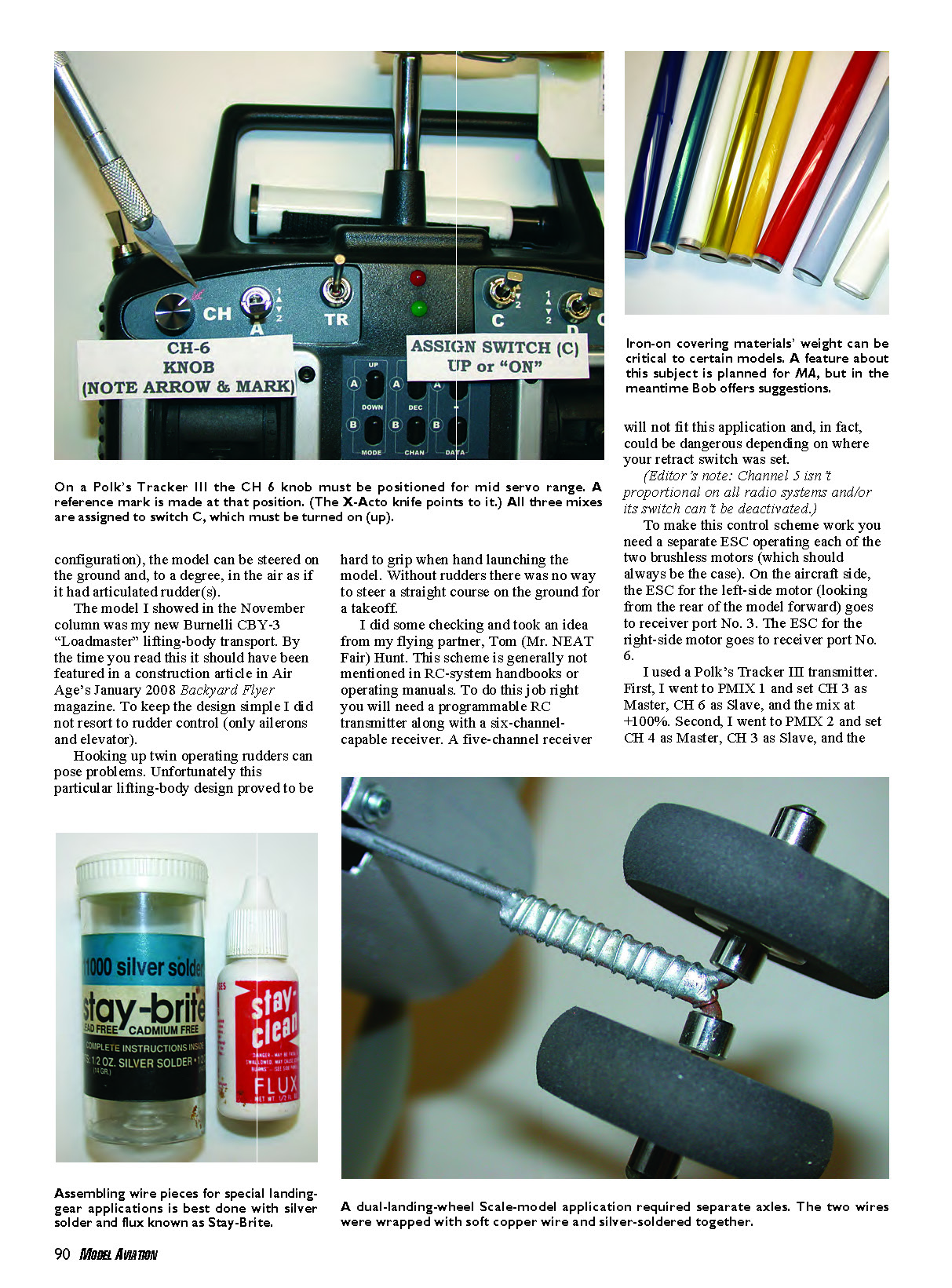
Knob/trim and switch setup (Tracker III specifics):
- On the Tracker III the CH 6 control is managed by a rotary knob. That channel must be preset to the neutral position. To do this:
- Plug a servo (with a long output arm) into aileron or elevator channel on the receiver and set the transmitter trim lever for that channel to neutral. Ensure no memory trim is in use and the servo output arm is at 90° to the servo case.
- Plug that servo into the receiver's CH 6 port and rotate the CH 6 knob to the midrange position so the servo arm is again at 90°. Mark the knob position and consider placing tape over the knob to prevent accidental movement.
- Go to Switch Assign in the transmitter menu and assign PMIX 1, PMIX 2, and PMIX 3 to Switch C. With that switch in the upper position (No. 1), all three mixes will be activated. Leave that switch alone once set.
How it works in use:
- With this setup, your transmitter throttle stick will run both motors together from idle to full for normal flight.
- Rocking the transmitter rudder control stick side to side will vary the motors' speeds. For example, applying right rudder will make the left motor run faster than the right, producing differential steering for ground steering and some in-flight yaw control.
Applicability:
- These instructions apply to a Polk’s Tracker III transmitter, but other brands of systems should work similarly. Consult other manufacturers for exact menu names and steps.
The success I had with this differential steering will prompt me to design more electric-powered twins.
Q334: Weights of iron-on covering materials
Q334: "I have an application for iron-on covering where the weight of the material may be critical. Is there any information available that compares the weights of the various iron-on covering material now on the market?"
A334: I thought this subject had been covered in the past. However, after an extensive search I realized that much has changed through the years: some older products are gone and newer ones have taken their place. The entire topic of iron-on covering material — weight, intended application, and application technique — needs a considerable update. This was discussed with AMA’s Publications Department, and a feature article is planned on this subject. In the meantime, I located an interesting weight-comparison table that is presented on the Internet.
Also recommended are two excellent books by Faye Stilley: Covering R/C Airplanes, volumes 1 and 2, published by Air Age Media. Faye is an iron-on-covering application master. The books are available from the AMA Supply and Service or via the AMA website (select “Shop AMA,” “Browse our Catalog,” “Books and DVDs,” then scroll to these two volumes).
Reference:
- Weights of Covering Materials: http://webpages.charter.net/rcfu/HelpsHints/IOCWeight.html
Q335: Solder for landing-gear wire and braces
Q335: "I'm having trouble soldering such things as landing gear wire and braces using conventional solder. I understand there may be a better type solder available to do this kind of job. Can you help me?"
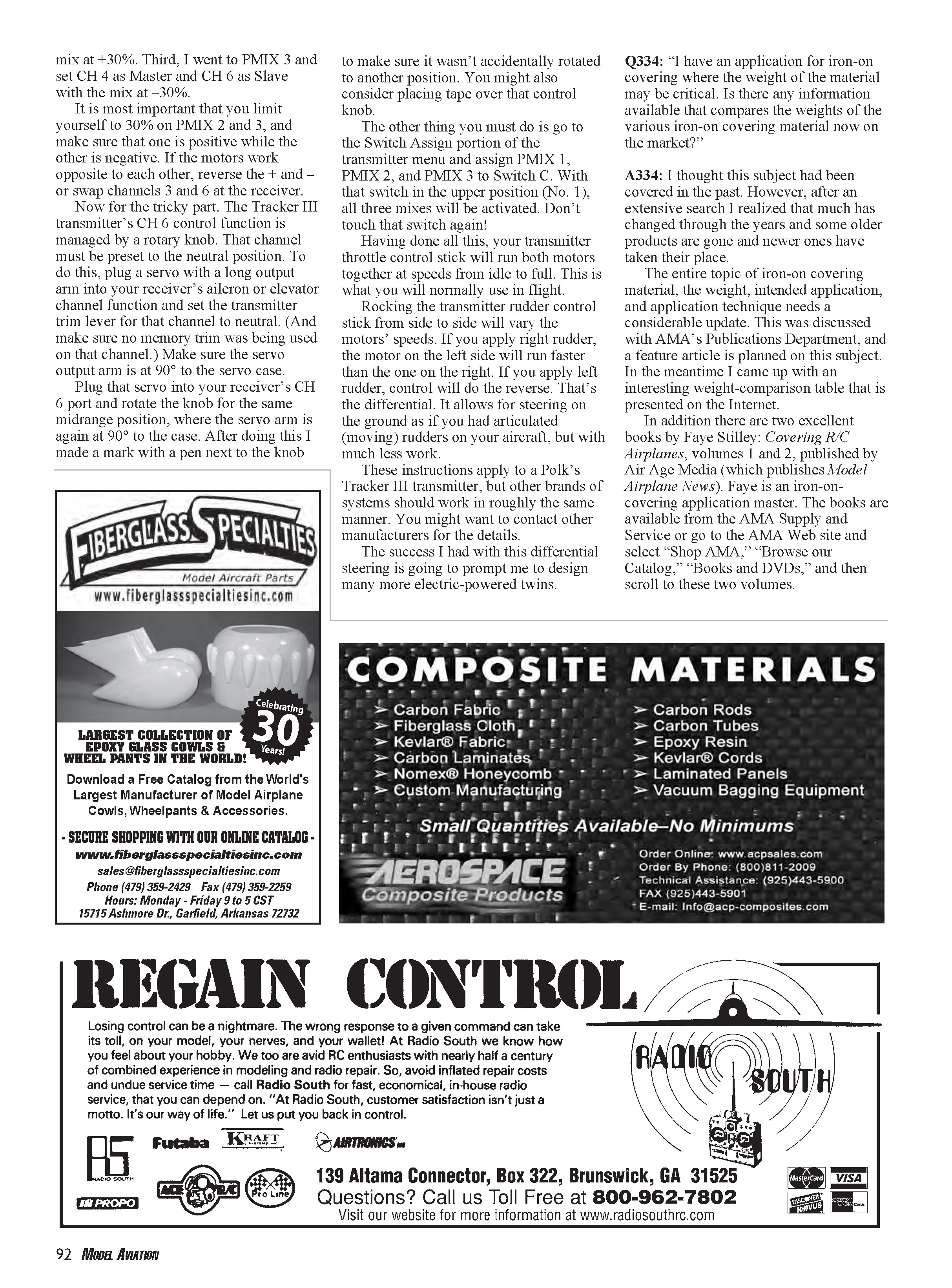
A335: Many modelers try to use common rosin-core (electrical) solder for joining wire such as landing gear. For these applications you should be using silver solder (also called hard solder). This type of solder has been on the market for years, often under the trade name Stay-Brite and manufactured by The Harris Products Group.
Recommended practice:
- Use a kit that includes silver solder and the appropriate liquid flux. One kit will last a long time; expect to pay around $12 plus shipping from some suppliers.
- Make sure you have enough heat. I use a 50-watt iron with a good-size chisel tip.
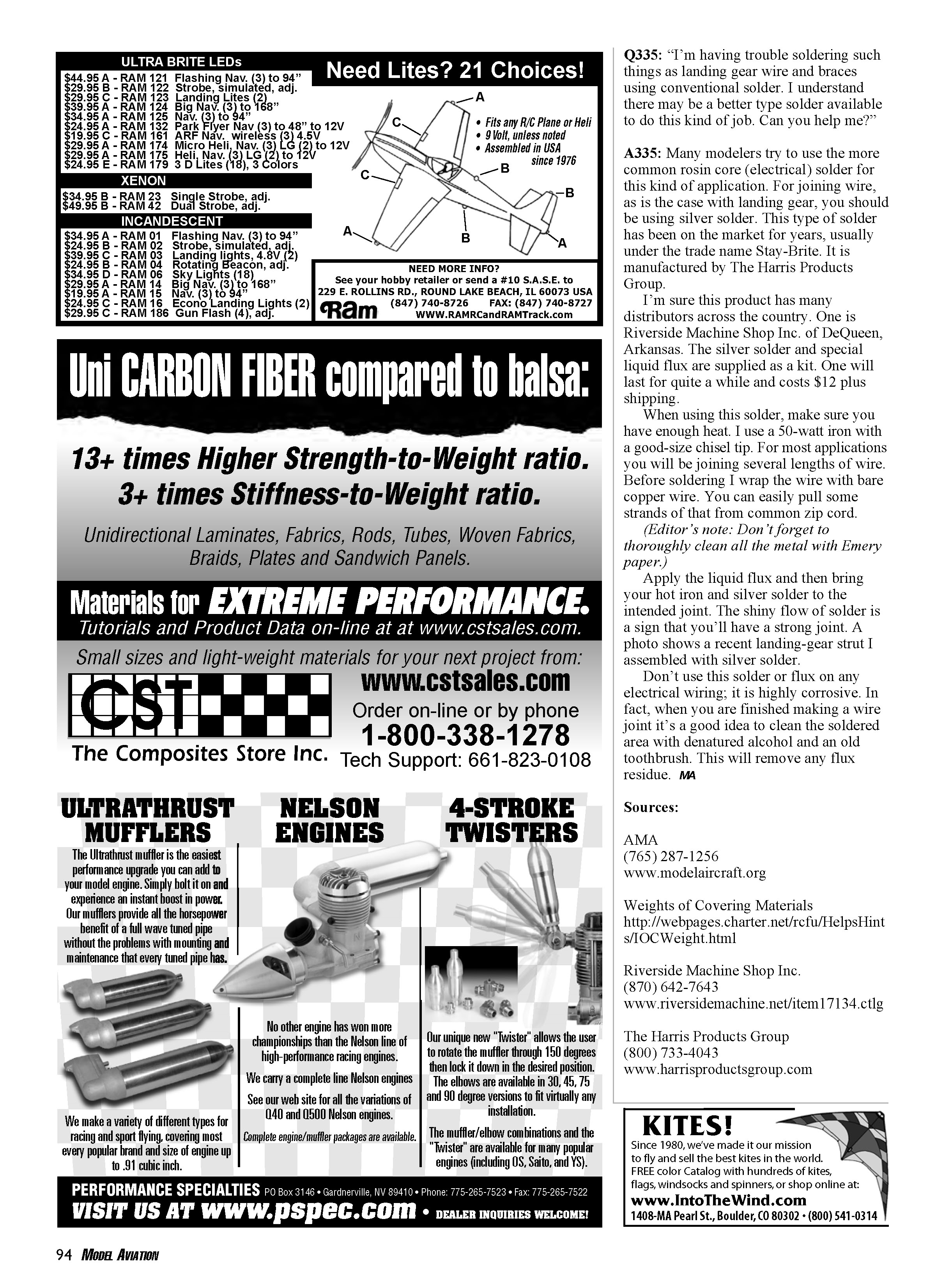
- For joining several lengths of wire, wrap the joint with bare copper wire (you can pull strands from common zip cord) to hold things together before soldering.
- Thoroughly clean all metal with Emery paper before applying flux and solder.
- Apply the liquid flux, then bring your hot iron and silver solder to the intended joint. A shiny flow of solder indicates a strong joint.
- After soldering, clean the area with denatured alcohol and an old toothbrush to remove flux residue; the flux used with silver solder is highly corrosive.
Warnings:
- Do not use this solder or flux on electrical wiring; it is highly corrosive and not suitable for electrical joints.
A photo in the original article shows a recent landing-gear strut assembled with silver solder.
Sources and contacts:
- AMA: (765) 287-1256, www.modelaircraft.org
- Riverside Machine Shop Inc.: (870) 642-7643, www.riversidemachine.net/item17134.ctlg
- The Harris Products Group: (800) 733-4043, www.harrisproductsgroup.com
Transcribed from original scans by AI. Minor OCR errors may remain.

