
Frequently Asked Questions - 2009/10
Separating Deans Ultra connectors
Bob Aberle | [email protected]
PLEASE WRITE IN with your questions, since that is the only way we can keep this column format going. When referring to published Qs and As (for follow-ups), provide the number as a reference.
References to addresses and Web sites are placed in a group, separate from the text, at the end of this column under "Sources."
Q418
"I happen to like the popular Deans Ultra connectors but have a hard time separating the two mating halves because the fit is so tight. I've seen a suggestion that employs nylon-fishing line that helps you pull the two halves apart. I've also seen your March 2009 FAQ column (page 83) where you referenced the Duralite Flight Systems Ultra connectors with added grips.
However, that requires that you connect the pigtail leads into your aircraft wiring. So I'm still looking for something simple, yet effective. Do you have any more suggestions?"
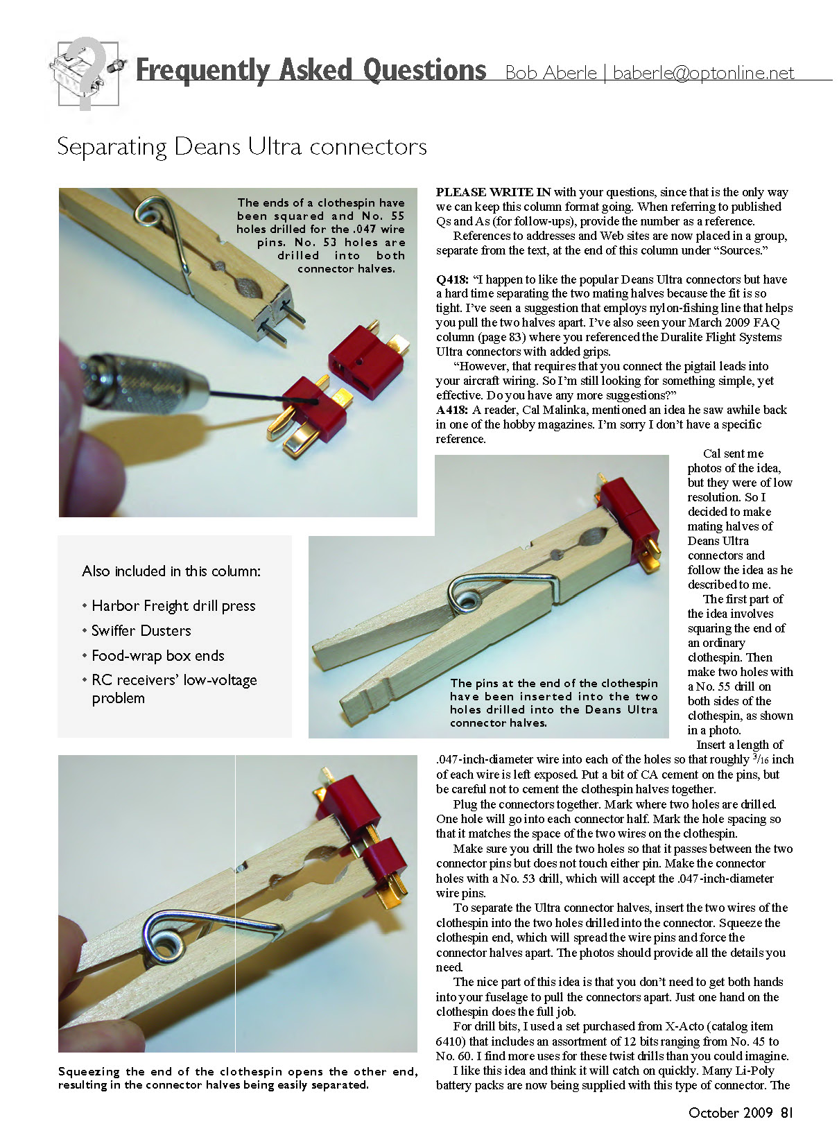
A418: A reader, Cal Malinka, mentioned an idea he saw awhile back in one of the hobby magazines. I don't have the specific reference, but Cal sent photos and described the idea. I made mating halves of Deans Ultra connectors and followed his method. The technique is simple and works well.
Steps to make the clothespin separator:
- Square the end of an ordinary wooden clothespin.
- Drill two holes through both sides of the clothespin using a No. 55 drill.
- Insert a length of .047-inch-diameter wire into each hole so roughly 3/16 inch of each wire is left exposed.
- Put a bit of CA cement on the pins—be careful not to cement the wood halves together.
- Plug the Deans Ultra connector halves together and mark where the two holes should be drilled in the connector halves. One hole goes in each connector half.
- Mark the hole spacing so it matches the spacing of the two wires on the clothespin. Drill the connector holes so the wires pass between the two connector pins without touching them.
- Use a No. 53 drill for the connector holes; a No. 53 will accept the .047-inch wire pins.
To separate the Ultra connector halves, insert the two clothespin wires into the drilled holes in the connector, then squeeze the clothespin end. The wires spread and force the connector halves apart. The nice part of this idea is you don't need two hands inside the fuselage—one hand on the clothespin does the job.
Notes and tools:
- Drill bits: I used a set from X-Acto (catalog item 6410) with bits No. 45 to No. 60. These twist drills are useful for many tasks.
- The Ultra connector is popular on many Li-Poly battery packs. It solders easily and needs no special crimping tool.
I recently visited a large Harbor Freight store just off I-95 in Dillon, South Carolina, and bought a drill press for slightly more than $50. It may not be heavy-duty, but it should last for our modeling needs; I used it to drill the holes in the Ultra connectors, which made the job easy. Harbor Freight also carries inexpensive modeler-type rotary tools and accessory kits—get a catalog or check their Web site.
Q419
"I've heard of many suggestions for getting fuel residue off my model aircraft. Usually it involves a solvent, like Windex and paper towels. But my electric-powered aircraft and my sailplanes just get dirty; they don't really need a solvent. Can you recommend something like a household duster?"
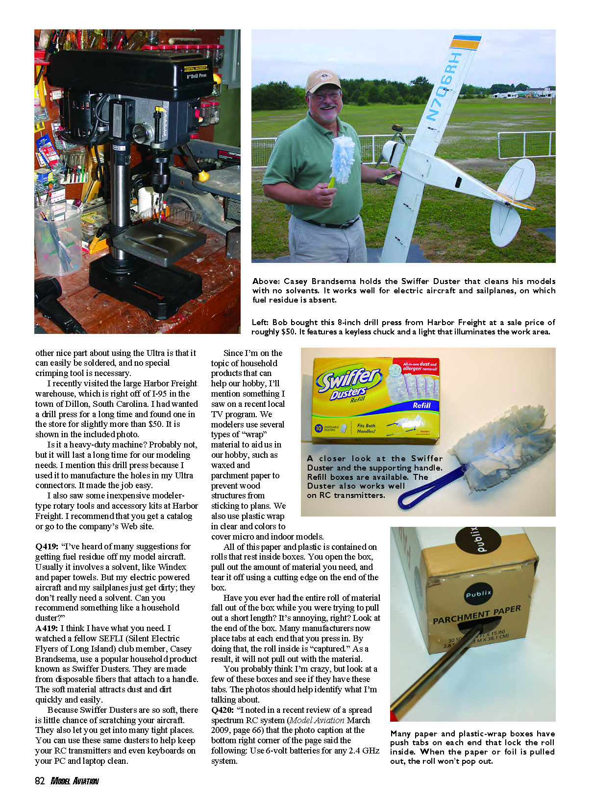
A419: Yes. A club member, Casey Brandsema, uses Swiffer Dusters for cleaning models. They are disposable fiber dusters that attach to a handle; the soft material attracts dust and dirt quickly and easily. Because they are so soft, they are unlikely to scratch aircraft surfaces and can reach into tight places. They also work well for cleaning RC transmitters and computer keyboards.
A related household tip: many rolls of wrap (waxed or parchment paper, plastic wrap, foil) come in boxes with cutting edges. Some manufacturers now include push tabs on the ends of the box that lock the roll inside so it won't pop out when you pull a short length. Check the ends of the boxes you use—these tabs are handy and can save frustration.
Q420
"I noted in a recent review of a spread spectrum RC system (Model Aviation March 2009, page 66) that the photo caption at the bottom right corner of the page said the following: 'Use 6-volt batteries for any 2.4 GHz system.' Is this true? I use 8-cell NiMH battery packs for my receivers."
A420: That caption is misleading. Most receiver manuals specify 4.8 to 6 volts for normal operation. Some receivers have onboard voltage regulators and will tolerate up to 7.2 volts, but 9.6 volts from an 8-cell NiMH pack is too high for most receivers and can damage them unless the receiver documentation specifically states it will accept that voltage. If you need more capacity, use a proper voltage regulator, a battery eliminator circuit (BEC), or a battery pack that delivers the correct voltage.
Sources
- Harbor Freight
Phone: (800) 444-3353 www.harborfreight.com
- Peak Electronics
Phone: (800) 532-0092 www.siriuselectronics.com
Transcribed from original scans by AI. Minor OCR errors may remain.

