
Frequently Asked Questions
Bob Aberle | [email protected]
Twin float installation and options
Please write in with your questions; that is the only way we can keep this column format going. When referring to published Qs and As (for follow-ups), provide the number as a reference.
Contact information for resources mentioned within the text are placed in a group, separate from the text, at the end of this column under “Sources.”
Q425:
“I remember seeing a while back in your column a reference to a twin float installation on park flyer and indoor size aircraft. I can’t find that article.
Can you point me to it and add any additional information that might help me install a set of floats on my model?”
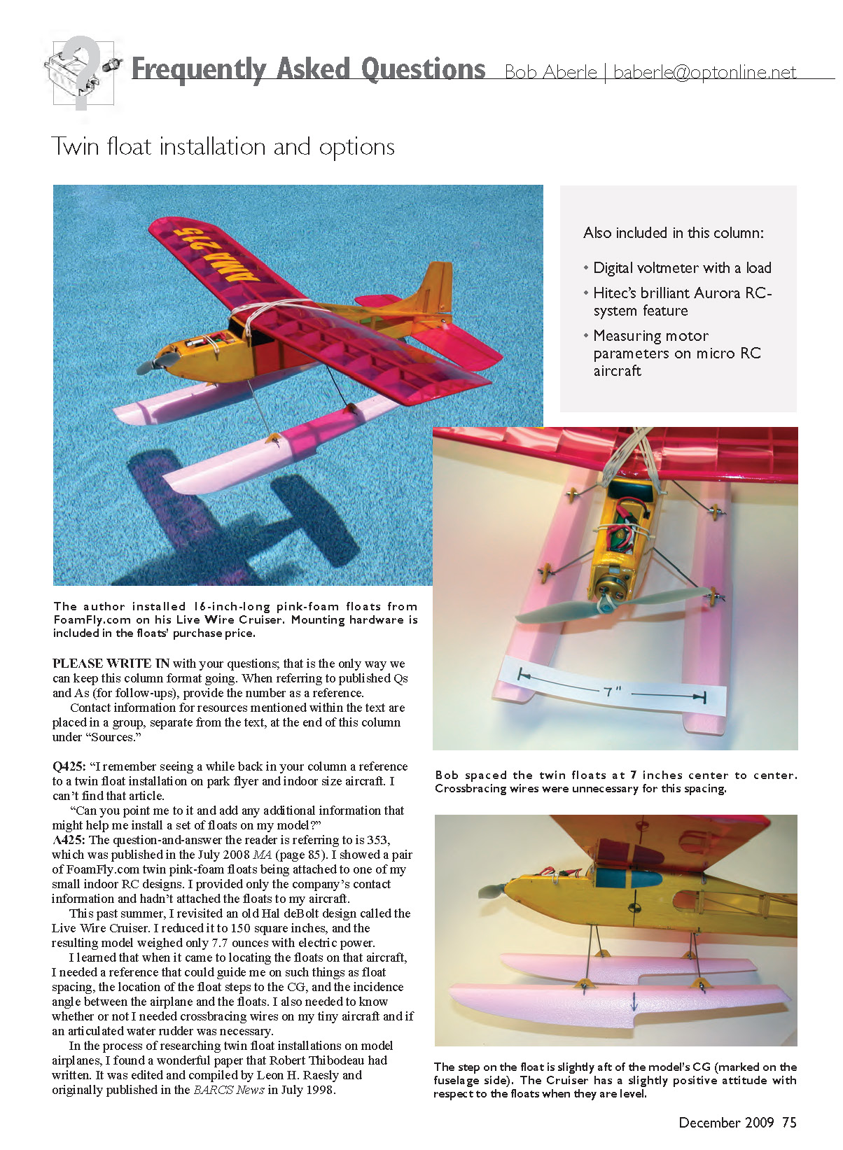
A425: The question-and-answer the reader is referring to is Q353, which was published in the July 2008 MA (page 85). I showed a pair of FoamFly.com twin pink-foam floats being attached to one of my small indoor RC designs. At that time I provided only the company’s contact information and hadn’t attached the floats to my aircraft.
This past summer I revisited an old Hal DeBolt design called the Live Wire Cruiser. I reduced it to 150 square inches, and the resulting model weighed only 7.7 ounces with electric power.
When locating the floats on that aircraft I needed a reference to guide me on float spacing, the location of the float steps relative to the CG, and the incidence angle between the airplane and the floats. I also needed to know whether crossbracing wires were necessary on a tiny aircraft and whether an articulated water rudder was required.
In the process of researching twin-float installations on model airplanes, I found a useful paper by Robert Thibodeau, edited and compiled by Leon H. Raesly, originally published in BARCS News in July 1998. The document is titled “Float Selection and Fine Tuning Your Float Plane Set‑Up.” In the Sources listing I’ve included the website where you can obtain this document; the address is long and, if you have trouble opening it, e-mail me and I’ll send the link.
Installing a pair of 16‑inch pink‑foam floats added only 1.1 ounces to my Live Wire Cruiser, bringing the total flying weight to 8.8 ounces. Crossbracing wires were unnecessary for this size aircraft, and I did not employ a water rudder.
Remember that to maneuver the aircraft while it’s in the water you must keep speed up (a technique called “plowing”). You also need more power than you would for land flying. The final motor-power input was 39 watts. With the weight of my model that resulted in a power loading of about 81 watts per pound, and the Live Wire Cruiser flew great. A construction article for this aircraft, with full‑size plans, was published in the December 2009 Fly RC magazine.
Q426:
“I read recently in your column that we should all be checking our RC receiver batteries before flying. You stated that the proper way to do this was to use a voltmeter that applies a load to the batteries.
The one meter that you recommended gave three choices of load current, but it cost quite a bit. Can you recommend a more economical substitute?”
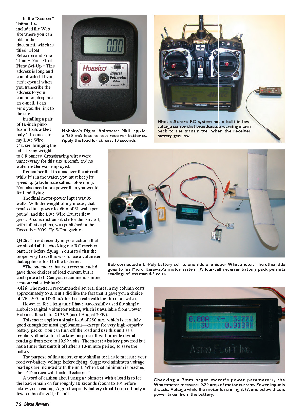
A426: The meter I recommended several times costs approximately $70 and offers selectable loads of 250, 500, or 1000 mA. For a less expensive option I have successfully used the Hobbico Digital Voltmeter MkIII, available from Tower Hobbies. It sold for $19.99 (as of August 2009).
This meter applies a single 250 mA load, which is adequate for most applications except very high‑capacity battery packs. You can turn off the load and use it as a regular voltmeter; it reads 0 to 19.99 volts. The meter is battery powered and has an auto-off timer after 10 minutes to save battery.
The purpose of a meter like this is to measure receiver-battery voltage before flying. Suggested minimum voltage readings are included with the unit; when the minimum is reached, the LCD will flash “Recharge.”
A caution about using a voltmeter with a load: let the load remain on for roughly 10 seconds before taking your reading. A good-capacity battery should drop only a few tenths of a volt under load. A battery with poor capacity will show a rapid voltage falloff; if you observe that, do not fly and test the battery for capacity with a device such as the West Mountain Radio CBA II or CBA III.
I’m always concerned about receiver voltage dropping to the point where the receiver quits or, with some spread-spectrum receivers, temporarily shuts down and requires rebooting. That’s why I recommend testing receiver batteries (if using a separate battery) before every flight.
On a related note, I received a Hitec RCD USA Aurora digital spread-spectrum system that includes a seven-channel Optima receiver. I learned the receiver is actually a transceiver: it can accept a signal from the transmitter and send a signal back. Hitec built a low-voltage sensor into the receiver circuit. If the receiver voltage drops below about 4.4 volts, the receiver sends a warning signal to the transmitter, which then alerts the pilot to land.
The receiver sensor accepts voltage sources from four- or five-cell battery packs, Li‑Poly packs, and even a BEC as used in electric power. This feature helps protect pilots from receiver low-voltage situations across various setups. I applaud Hitec for this development and hope other manufacturers adopt similar receiver-power warning systems.
Q427:
"Like many people I have enjoyed flying my ParkZone Cessna, but after a while wanted to remove the power and RC system and move on to other aircraft. I never did get a handle on parameters like motor current, power input and so on.
This info would help me more if I decided to go to a higher power motor, which might, in turn, require a higher capacity battery cell. How would I go about measuring these needed parameters?"
A427: As shown in an accompanying photo, I did what you’re planning. I designed a reduced-size Kerswap Old-Timer replica with 50 square inches of wing area and a total weight of 35 grams. The design is featured in the September 2009 Micro RC World Online Magazine.
The Cessna brushed motor drew about 275 mA and roughly 1 watt of input power. That was fine for a 16-gram Cessna, but not for a 35-gram Kerswap. I switched to a 7 mm red geared pager motor from BSD Micro RC and wanted to measure the motor current and power input for the propeller I selected.
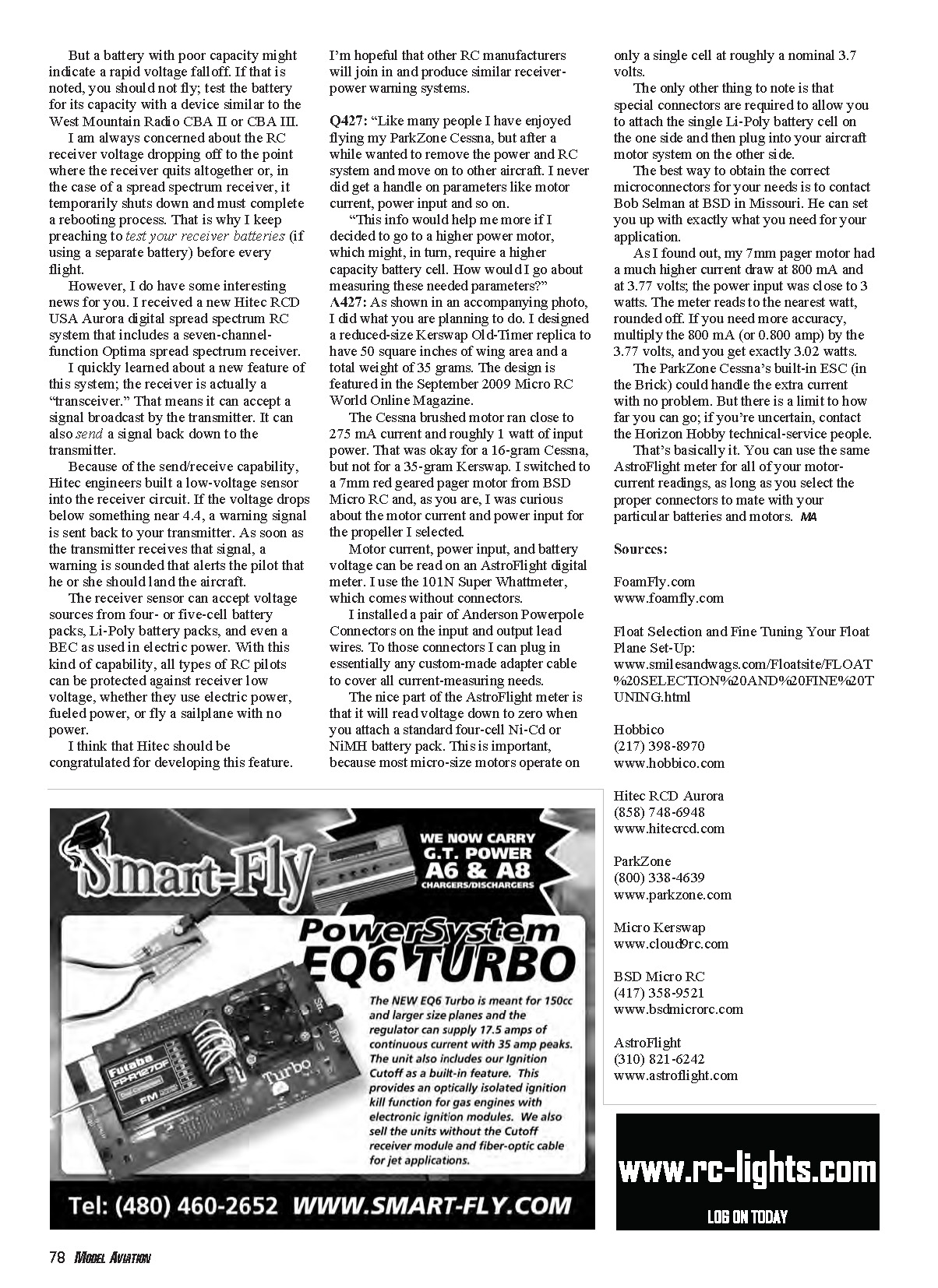
Motor current, power input, and battery voltage can be read on an AstroFlight digital meter. I use the 101N Super Whattmeter, which comes with connectors. I installed a pair of Anderson Powerpole connectors on the meter’s input and output leads so I can plug in adapter cables for various setups.
The AstroFlight meter reads voltage down to zero, which is important because many micro motors run on a single cell around a nominal 3.7 volts. Special connectors are required to attach a single Li‑Poly cell on one side and plug into your aircraft motor system on the other. Contact Bob Selman at BSD in Missouri for the correct microconnectors for your needs.
My 7 mm pager motor drew about 800 mA at 3.77 volts; the meter rounded the input to 3 watts. For greater accuracy multiply 0.800 A × 3.77 V = 3.02 watts.
The ParkZone Cessna’s built-in ESC (in the “Brick”) could handle the extra current with no problem. If you’re unsure about limits, contact Horizon Hobby technical service.
In short: use a meter like the AstroFlight Super Whattmeter with appropriate connectors to measure motor current, voltage, and power input for your specific batteries and motors.
Sources
- FoamFly.com — www.foamfly.com
- Float Selection and Fine Tuning Your Float Plane Set‑Up:
www.smilesandwags.com/Floatsite/FLOAT%20SELECTION%20AND%20FINE%20TUNING....
- Hobbico — (217) 398-8970 — www.hobbico.com
- Hitec RCD Aurora — (858) 748-6948 — www.hitecrcd.com
- ParkZone — (800) 338-4639 — www.parkzone.com
- Micro Kerswap — www.cloud9rc.com
- BSD Micro RC — (417) 358-9521 — www.bsdmicrorc.com
- AstroFlight — (310) 821-6242 — www.astroflight.com
Transcribed from original scans by AI. Minor OCR errors may remain.

