
Frequently Asked Questions - 2010/07
Notes to readers
Please write in with your questions, since that is the only way we can keep this column format going. When referring to published Qs and As (for follow-ups), provide the number as a reference.
References to addresses and Web sites are placed in a group, separate from the text, at the end of this column under "Sources."
Q428: CA cements: a suggestion
Q: I have been using a variety of CA-type cements for years. The extremely fast curing time certainly enables me to build faster. But one of the things that has bothered me for some time is the fact that the tips of typical CA cement bottles clog much too easily.
I seem to constantly be inserting pins into the nozzle ends to get the cement to flow again. Since you obviously do a lot of building, what would you suggest to solve this problem?
A: I stumbled upon an idea almost by accident. I saw a cement dispenser a few years ago while attending the WRAM (Westchester Radio AeroModelers) Show in White Plains, New York. It was obtained from the surgical-supply industry.
This dispenser had a plastic bulb at one end and a thin tube at the other. The idea was to insert the tube into a bottle of CA, squeeze the bulb and release it, and that would suck the cement out of the bottle.
You could adjust the flow of adhesive coming out of the tubing by pulling on it with pliers to make it thinner in diameter. This worked well, but the tubing still became clogged easily.
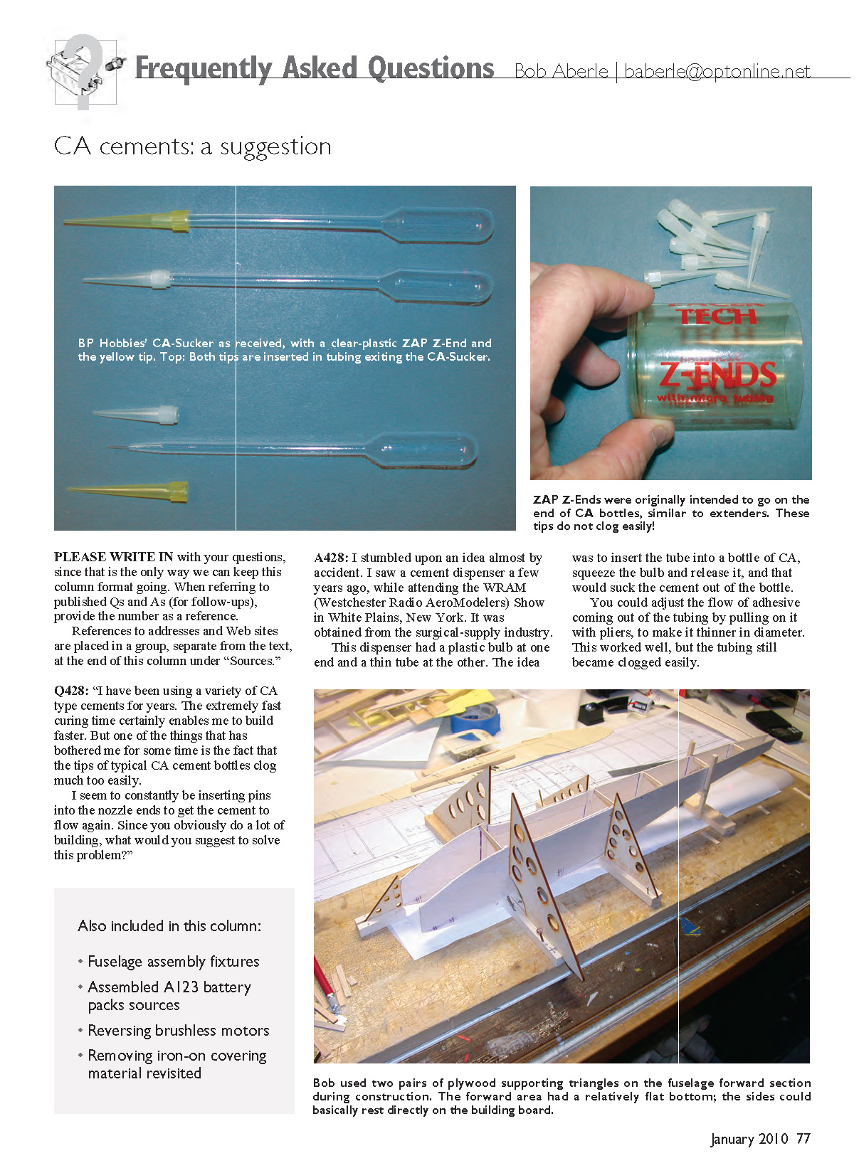
I recently purchased some plastic dispensers from BP Hobbies that are called "CA-Suckers," but I noticed that the tubing on those new dispensers was considerably larger in diameter—so much larger that you couldn't pull on them. I thought I really had a problem. But in my supply drawer I found two types of CA bottle tips that I had purchased over the years. I learned that I could cut off the end of the CA-Sucker and place one of the bottle tips on the end of the tubing. In both cases, the tip fit snugly—exactly what I needed. This works the same way: squeeze the bulb, with the tip placed inside the CA bottle, and release it. For some reason, these tips do not clog. I built an entire aircraft and experienced no clogging during the project. If you get excess CA on the end of the tip, you can pull it off with pliers.
I cannot find a source for the yellow tip shown at this time. However, the clear tips come from Pacer Technology, which makes the Zap brand of products. These tips are called "Z-Ends" and are catalog item PT-18. See the Sources section for contact information.
Q429: Fuselage assembly jig for sloping bottoms
Q: I noticed in FAQ-415 the supporting plywood triangles you used as a fuselage assembly jig. I tried your idea but found that it worked best on fuselages that had a straight or flat top or bottom. What do you recommend when the fuselage has a sloping bottom?
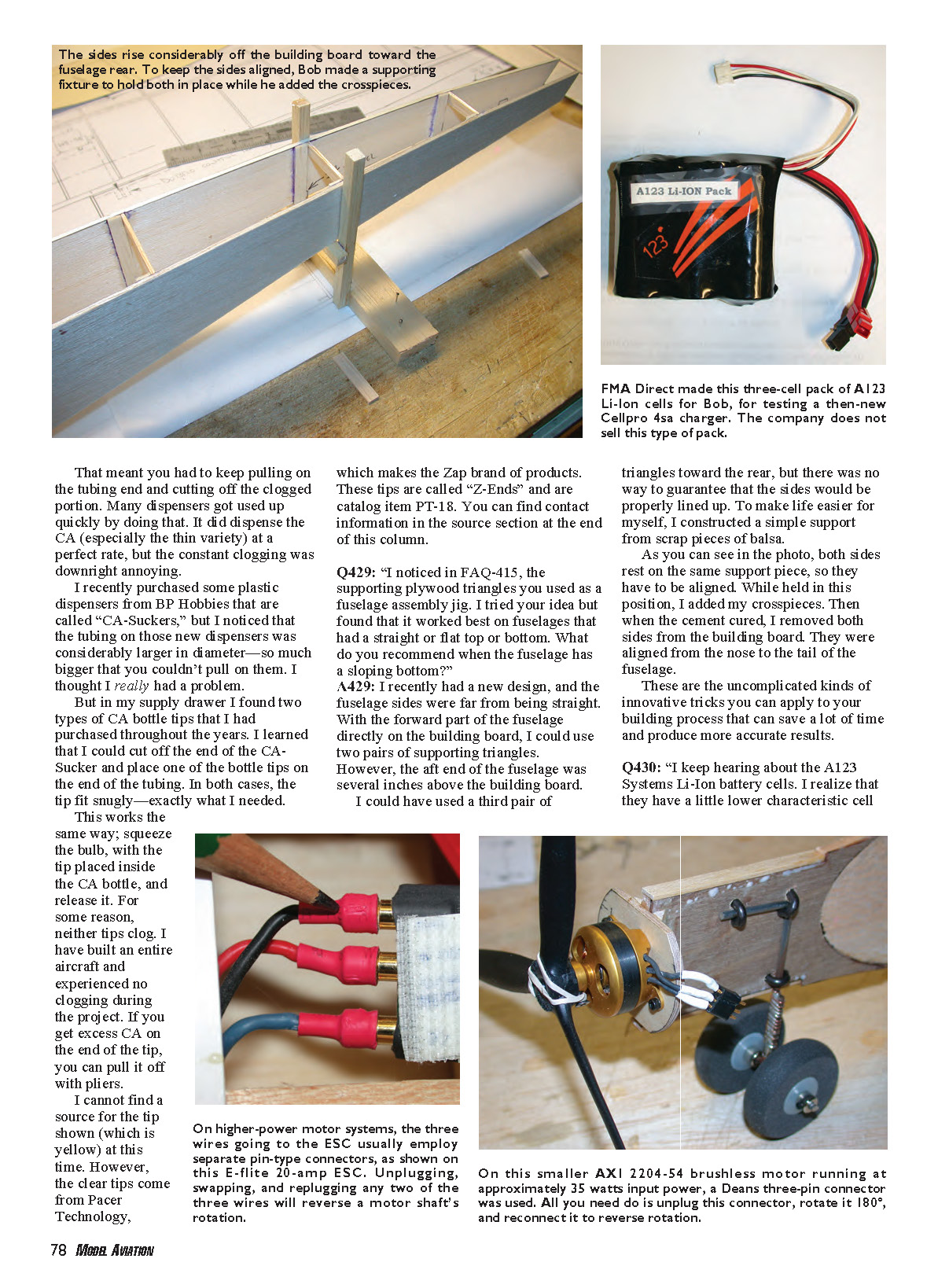
A: I recently had a new design where the fuselage sides were far from straight. With the forward part of the fuselage directly on the building board, I could use two pairs of supporting triangles. However, the aft end of the fuselage was several inches above the building board.
I could have used a third pair of triangles toward the rear, but there was no way to guarantee that the sides would be properly lined up. To make life easier for myself, I constructed a simple support from scrap pieces of balsa.
Both sides rest on the same support piece, so they must be aligned. While held in this position, I added my crosspieces. Then, when the cement cured, I removed both sides from the building board. They were aligned from the nose to the tail of the fuselage.
These are the uncomplicated kinds of innovative tricks you can apply to your building process that can save a lot of time and produce more accurate results.
Q430: Sources for A123 Systems cells and packs
Q: I keep hearing about the A123 Systems Li-ion battery cells. I realize that they have a slightly lower characteristic cell voltage and weigh a little more than Li-Poly batteries, yet many are successfully using these cells.
I decided to purchase a few packs and discovered that assembled A123 packs are somewhat hard to find. If you were buying any of these packs for yourself, where would you go?
A: I thought this would be an easy question to answer, but it wasn't. I looked at several web sites I’m familiar with and couldn't find anyone selling assembled A123 packs.
I have been using a three-cell, 2300 mAh (9.9 V) pack with a balance connector that the people at FMA Direct hand-made for me while I was testing the latest version of the company's Cellpro 4sa charger. FMA Direct does not sell A123 cell battery packs.
Next I contacted Red Scholefield, MA's battery columnist. When A123 cells became available, Red and I shared a batch of six and made our own three-cell packs. Red told me he buys DeWalt 36-volt drill motor packs from eBay, breaks them down, and assembles them into packs for his modeling needs. He also mentioned Hangtimes Hobbies as a source for assembled packs that are primarily for RC and ignition applications.
I wanted to duplicate what I had received from FMA Direct and found exactly that at BP Hobbies. They have packs assembled into two-, three-, and four-cell configurations, with main power leads as well as balance-node connectors that mate with E-Tec/PolyQuest balance adapters. I'm sure there are more suppliers, but this gives you a starting point.
Q431: Reversing brushless motor rotation
Q: It is my understanding that when dealing with brushless motors that have three exiting wires, you can reverse the motor rotation by simply swapping any two of the three wires. Well, I did that, but to be thorough I swapped two wires, then two more. That didn't work. What did I do wrong?
A: The likely cause of your problem is, coincidentally, a bad connector or a broken wire.
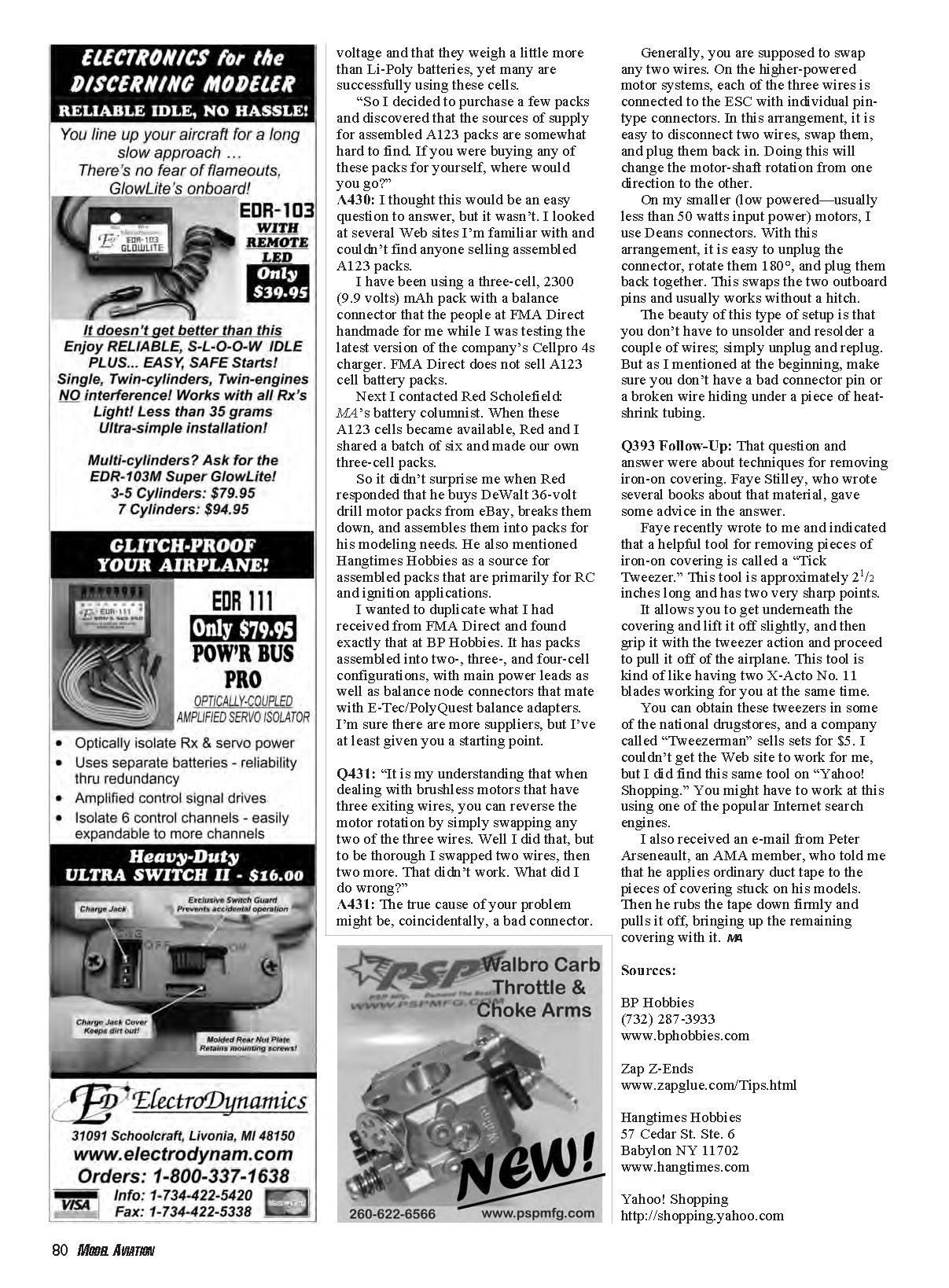
Generally, swapping any two wires will reverse the motor rotation. On higher-powered motor systems, each of the three wires is connected to the ESC with individual pin-type connectors. In this arrangement, it's easy to disconnect two wires, swap them, and plug them back in; doing so will reverse the motor-shaft rotation.
On smaller, lower-powered motors (usually less than about 50 W input), I often use Deans connectors. With this arrangement, unplug the connector, rotate it 180°, and plug it back together. This rotates the two outboard pins and usually reverses rotation without a hitch.
The beauty of these methods is you don't have to unsolder and resolder wires—simply unplug and replug. But be sure there isn't a bad connector pin or a broken wire hidden under a piece of heat-shrink tubing.
Q393 Follow-Up: Removing iron-on covering
This was a follow-up to Q393 about techniques for removing iron-on covering. Faye Stilley, who wrote several books about covering material, gave useful advice in the original answer.
Faye recently wrote to say that a helpful tool for removing small pieces of iron-on covering is called a "Tick Tweezer." This tool is approximately 2.5 inches long and has two very sharp points. It allows you to get underneath the covering and lift it slightly, then grip it with the tweezer action and pull it off the airplane. The tool is like having two X-Acto No. 11 blades working together.
You can obtain these tweezers in some national drugstores; the company Tweezerman sells sets for about $5. I couldn't get Tweezerman's web site to work for me, but I did find the same tool via Yahoo! Shopping. You might also try one of the popular internet search engines.
I also received an email from Peter Arsenault, an AMA member, who said he applies ordinary duct tape to pieces of covering stuck on his models. He rubs the tape down firmly and pulls it off, bringing up the remaining covering with it. — MA
Sources
- BP Hobbies
- (732) 287-3933
- www.bphobbies.com
- Zap Z-Ends
- www.zapglue.com/Tips.html
- Hangtimes Hobbies
- 57 Cedar St. Ste. 6
- Babylon, NY 11702
- www.hangtimes.com
- Yahoo! Shopping
- http://shopping.yahoo.com
Transcribed from original scans by AI. Minor OCR errors may remain.

